Oil filter and refrigerating system

An oil filter and filter element technology, applied in the field of filters, can solve the problems of high cost, prone to deflection, failure of filter element components, etc., and achieve the effects of reduced manufacturing cost, stable and reliable positioning, and not easy to be deflected.

Active Publication Date: 2012-10-24
ZHEJIANG SANHUA INTELLIGENT CONTROLS CO LTD
View PDF5 Cites 10 Cited by
  • Summary
  • Abstract
  • Description
  • Claims
  • Application Information

AI Technical Summary

Problems solved by technology

[0008] For the oil filter with this structure, since the filter element part and the second support block 8-2 are axially positioned through right-angled steps, the distance between the stress points is small, figure 1 Middle C is the stress point of the filter element, which causes the filter element to be less stable and prone to deflection when it is pressed by the spring 10 at the inlet end. If the filter element is deflected, the front end cover 2 and the shell During the welding process of body 1, it is easy to cause partial failure of filter elements due to high temperature heating, such as figure 1 As shown, position A is the welding position between the front end cover 2 and the housing 1, and position B is the position where the filter elements are prone to heat failure; and the second support block 8-2 needs to be welded on the outlet joint 7, the welding process is complicated, the structure is complex, and the cost higher
[0009] In addition, a T-shaped sealing ring 9-2 is used for sealing between the filter element part and the second support block 8-2, and the sealing part of the end part is in plane contact, the area is too large, and the sealing performance is poor

Method used


Image

  • Oil filter and refrigerating system
  • Oil filter and refrigerating system
  • Oil filter and refrigerating system

Examples


Embodiment Construction

[0028] In order to enable those skilled in the art to better understand the technical solutions of the present invention, the present invention will be further described in detail below in conjunction with the accompanying drawings and specific embodiments.

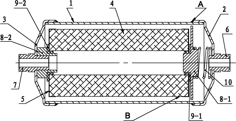
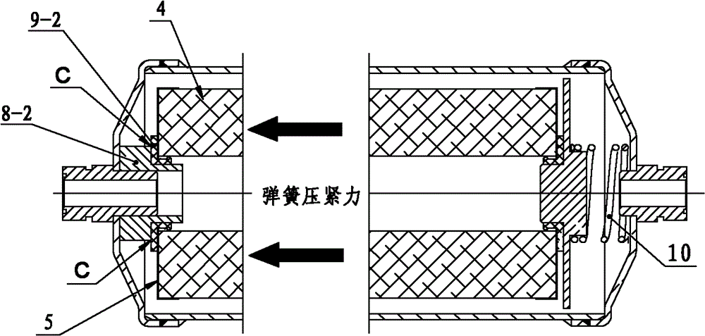
[0029] Please see Figure 4 , Figure 5 , Figure 4 A structural schematic diagram of a specific embodiment of the oil filter provided by the present invention; Figure 5 for Figure 4 Schematic diagram of the force-bearing structure of the middle filter element.

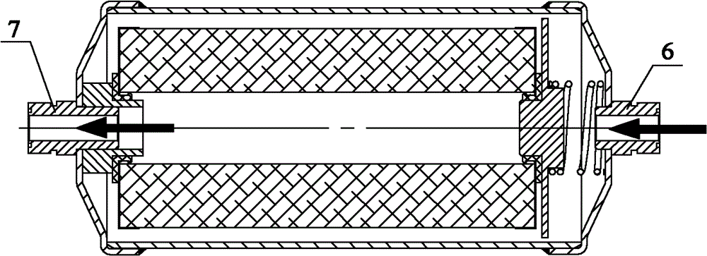
[0030] Such as Figure 4 As shown, the oil filter provided by the present invention includes a housing 1, a front end cover 2, a rear end cover 3 and filter elements, the front end cover 2 is provided with an inlet joint 6, the rear end cover 3 is provided with an outlet joint 7, and the front end cover 3 is provided with an outlet joint 7. 2. The rear end caps 3 are respectively welded to the two ends of the housing 1, the filter element parts are placed ...


PUM


Abstract

The present invention relates to the technical field of filter, and especially discloses an oil filter with a stably and reliably positioned filter component. The oil filter comprises a shell, a front end cover, a rear end cover and a filter component. The front end cover is provided with an inlet joint; the rear end cover is provided with an outlet joint; and end face of an outlet end of the filter component abuts against an inner side surface of the rear end cover; and the outlet joint and the outlet of the filter component form a socket cooperation. The oil filter can realize stability and reliability of positioning of the filter component; deflection is not likely to happen; and during a welding process of the front end cover and the shell, failure of the filter component caused by local high temperature and heating will not happen. A second supporting seat between the outlet joint and the filter component, and a welding process on the second supporting seat and the outlet joint are canceled, so as to realize simple process, simple structure of the oil filter and low manufacturing cost. The invention also discloses a refrigerating system with the oil filter.

Description

technical field [0001] The invention relates to the technical field of filters, in particular to an oil filter with stable and reliable positioning of filter elements. The invention also relates to a refrigeration system with the above-mentioned oil filter. Background technique [0002] The oil filter in the refrigeration system is an oil filtering device, which is mainly used on the oil return pipeline of the compressor, such as the oil return pipeline of the compressor of the central air conditioner. The mixture of refrigerant and refrigerating oil from the compressor enters the inlet of the oil separator. After being separated by the oil separator, the refrigerant enters the condenser in an "oil-free" state, while the refrigerating oil is filtered by the oil filter and returns to the condenser. In the compressor, the oil filter can filter out the impurities in the refrigeration oil and prevent the impurities in the refrigeration oil from damaging the moving parts of the ...

Claims


Application Information

Patent Timeline
Patent Type & Authority Applications(China)
IPC IPC(8): B01D35/02B01D29/11F25B43/00
Inventor 俞志辉蒋伟伟
Owner ZHEJIANG SANHUA INTELLIGENT CONTROLS CO LTD
Why Eureka
Try Eureka