Carbon dioxide foam injecting device of oil well

A carbon dioxide, injection device technology, used in mixers with rotary stirring devices, transportation and packaging, wellbore/well components, etc. Low problems, to achieve the effect of novel structure, guaranteed foaming performance, and low cost

Active Publication Date: 2012-10-24
XIAN SUNWARD AEROSPACE MATERIAL CO LTD
View PDF6 Cites 20 Cited by
  • Summary
  • Abstract
  • Description
  • Claims
  • Application Information

AI Technical Summary

Problems solved by technology

[0002] In the petroleum industry, the earlier foam generators were mainly used in the foam well washing process. With the gradual research on foam in the field of oil drilling and production, my country has carried out profile control and water plugging by using foam fluid in most oil production bases. , acidified formation, cement cementing, fracturing, sand flushing, drilling, drainage and gas recovery, and foam steam flooding, etc., and achieved good results. Foam is a compressible gas-liquid mixture. From the point of view of theoretical analysis, there are still some deficiencies in the use of foam generators. They cannot withstand large pressures, and corrosion problems are not considered in the application of oil and gas field development. The low-density foam fluid produced by its structural design cannot Fully meet the needs of on-site production in the oil field, the foam quality is low, the foaming agent and the carbon dioxide liquid cannot be fully mixed, and the temperature cannot be adjusted according to actual needs, especially the carbon dioxide foam flooding injection wellhead CO 2 The foaming agent freezes and blocks surface pipelines and wellbores due to heat absorption during the transition from liquid to gas at -20°C

Method used


Image

  • Carbon dioxide foam injecting device of oil well

Examples


Embodiment Construction

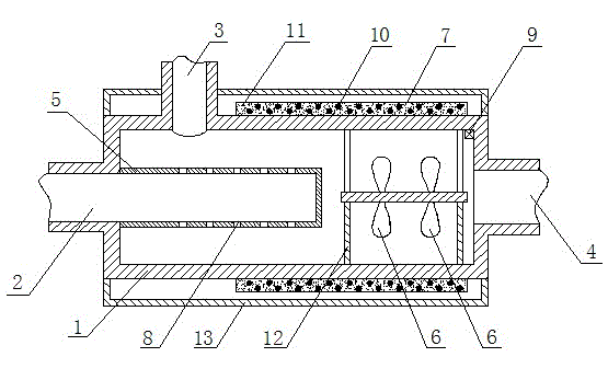
[0011] Attached below figure 1 To the oil well carbon dioxide foam injection device of the present invention, be further explained:

[0012] The oil well carbon dioxide foam injection device of the present invention is composed of a cylinder body 1, a carbon dioxide inlet 2, a dosing port 3 and a mixed liquid outlet 4, and one end of the cylinder body 1 is provided with a carbon dioxide inlet 2, and the other end is provided with a mixed liquid outlet 4 A dosing port 3 is provided on the side wall of the cylinder body 1 near the end of the carbon dioxide inlet 2; the carbon dioxide inlet 2 in the cylinder body 1 is connected to the spray pipe 5, and the spray pipe 5 is densely covered with spray ports 8, so that the liquid carbon dioxide can be sprayed. Effect.

[0013] A stirring paddle 6 is arranged on the fixed frame 12 in the space between the spray pipe 5 and the mixed liquid outlet 4 . The stirring paddle fully stirs the foaming agent entering the dosing port and the c...


PUM


Abstract

The invention provides a carbon dioxide foam injecting device of an oil well and relates to a mechanical device in an oil mine field. The carbon dioxide foam injecting device is composed of a cylinder body, a carbon dioxide inlet, a dosing port and a mixed liquid outlet. One end of the cylinder body is provided with the carbon dioxide inlet, the other end of the cylinder body is provided with the mixed liquid outlet, a side wall at one end of the cylinder body close to the carbon dioxide inlet is provided with the dosing port. The carbon dioxide inlet in the cylinder body is connected with a spraying pipe, and a stirring paddle is arranged on a fixing frame from the spraying pipe to a mixed liquid outlet space. The carbon dioxide foam injecting device of the oil well is novel in structure, low in construction cost and high-pressure-resisting, the cylinder body is made of stainless steel, and the material is OCr18Ni9 and can bear pressure of 25 MPa. Efficient flame retardant crystallized magnesium oxide is filled in a heater, an electric heat tracing band can heat a system at the temperature of 0-150 DEG C, and a temperature sensor externally-connected temperature control cabinet performs automatic control to a working state of an electric heating pipe. The carbon dioxide foam injecting device solves the problem of frozen blocking in the carbon dioxide foam oil-displacement process and effectively ensures the foaming performance of a carbon dioxide foam system.

Description

technical field [0001] The invention relates to a mechanical device on an oil field, in particular to a carbon dioxide foam injection device for an oil well. Background technique [0002] In the petroleum industry, the earlier foam generators were mainly used in the foam well washing process. With the gradual research on foam in the field of oil drilling and production, my country has carried out profile control and water plugging by using foam fluid in most oil production bases. , acidified formation, cement cementing, fracturing, sand flushing, drilling, drainage and gas recovery, and foam steam flooding, etc., and achieved good results. Foam is a compressible gas-liquid mixture. From the point of view of theoretical analysis, there are still some deficiencies in the use of foam generators. They cannot withstand large pressures, and corrosion problems are not considered in the application of oil and gas field development. The low-density foam fluid produced by its structural...

Claims


Application Information

Patent Timeline
Patent Type & Authority Applications(China)
IPC IPC(8): E21B43/22B01F5/18B01F7/06B01F3/04B01F15/06B01F25/70B01F27/71
Inventor 宋彬张大鹏路涛
Owner XIAN SUNWARD AEROSPACE MATERIAL CO LTD
Why Eureka
Try Eureka