
Grate-firing boiler with in-boiler two-level dedusting device

A technology for a dust removal device and a boiler, which is applied in the field of boilers, can solve the problems of decreased separation efficiency and insignificant effect of the initial smoke and dust emission concentration of the boiler, and achieves the effects of reducing heat loss, increasing continuous operation time and reducing wear and tear.

Inactive Publication Date: 2012-10-24
TAIYUAN BOILER GROUP
View PDF6 Cites 1 Cited by
  • Summary
  • Abstract
  • Description
  • Claims
  • Application Information

AI Technical Summary

Problems solved by technology

The separation device is divided into four rows of pipes from a row of pipes on the rear water wall, two of which have fins, and the fins cannot be made too wide due to temperature constraints, resulting in a short circuit in the high-temperature separation device and a decrease in separation efficiency; The separation device has only one stage of separation, which is effective in increasing the burnout rate of carbon in fly ash, but has no obvious effect on reducing the initial concentration of smoke and dust emissions from boilers

Method used


Image

  • Grate-firing boiler with in-boiler two-level dedusting device
  • Grate-firing boiler with in-boiler two-level dedusting device
  • Grate-firing boiler with in-boiler two-level dedusting device

Examples


Embodiment Construction

[0019] The present invention will be further described below in conjunction with the accompanying drawings and embodiments.

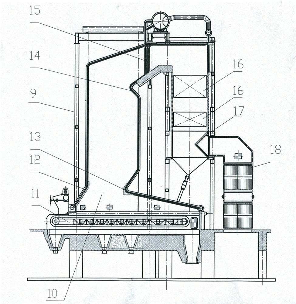
[0020] Such as figure 1 As shown, the present invention is a layer-fired boiler with a two-stage dust removal device in the furnace; it includes a furnace body 9, a furnace 10 in the furnace body, a fire grate 11, a front arch 12, a rear arch 13, a flame angle 14, and slag Tube separation device 15, economizer 16, inertial separation device 17, air preheater 18; the slag tube separation device is at the outlet of the furnace, and the inertial separation device is at the outlet of the economizer;

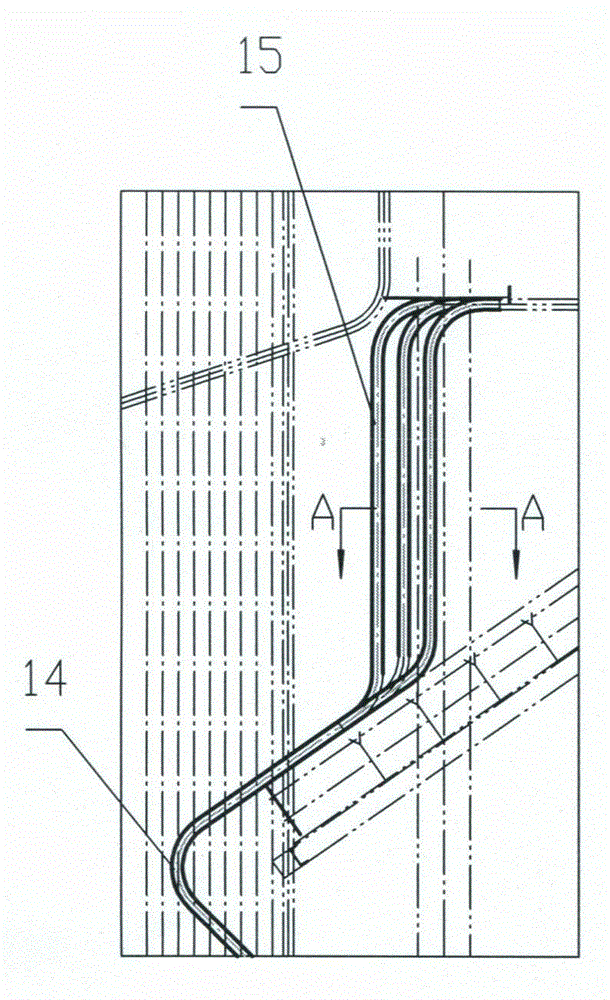
[0021] Such as figure 2 , 3 and Figure 4 As shown, the slag tube separation device at the furnace outlet is arranged in three rows of staggered arrangement by a row of rear water walls, and heat-resistant and wear-resistant fins 22 are welded on both sides of the slag tube 21; The heat cannot be transferred by the slag tubes in time to expand and deform,...


PUM


Abstract

The invention provides a grate-firing boiler with an in-boiler two-level dedusting device. The grate-firing boiler comprises a boiler body, a boiler hearth, a boiler grate, a front arch, a rear arch, a furnace arch, a crust block pipe separating device, a coal saver, an inertia separating device and an air preheater, wherein the boiler hearth, the boiler grate, the front arch, the rear arch, the furnace arch, the crust block pipe separating device, the coal saver, the inertia separating device and the air preheater are arranged in the boiler body. The grate-firing boiler is characterized in that the grate-firing boiler adopts twice separation, smoke is performed with primary separation through the crust block pipe separating device so as to separate most of crude particles and small amount of fine particles, and the crude particles and fine particles are rekindled after being fed into the boiler hearth through the furnace arch. The smoke performed with the primary separation moves downwards on the tail flue and then is returned back by the inertia separating device to be performed with secondary separation, the particles separated from the secondary separation are conveyed to the rear portion of the fire grate through air force to be rekindled. By means of the twice separation, mechanical incomplete combustion loss is reduced by 4%-6.5%, initial smoke discharging concentration of the boiler is reduced by more than 61%, abrasion of a tail heating surface is reduced, and continuous operation time of the device is added.

Description

technical field [0001] The invention belongs to the technical field of boilers, in particular to a layer-fired boiler for energy conversion with two-stage dust removal devices in the furnace. Background technique [0002] At present, the contradiction between the relatively low efficiency and high pollution of large chain boilers and energy saving, emission reduction and environmental protection has become increasingly prominent. However, the chain boiler has the advantages of not needing a complex pulverizing system, low investment, and easy operation. The development of dust removal technology in the furnace has become the key to the development of chain boilers with large capacity. The furnace dust removal chain boiler is mainly composed of grate, front arch, rear arch, flame angle, slag tube separation device, economizer, inertial separation device, and air preheater. [0003] Domestically, a high-temperature separation device is disclosed with a public invention patent...

Claims


Application Information

Patent Timeline
Patent Type & Authority Applications(China)
IPC IPC(8): F23B80/00F23J1/00F23J3/00
Inventor 成志建刘爱成鞠华鹏林毅生韩强孟祥定
Owner TAIYUAN BOILER GROUP
Learn More