Combustion method and system for realizing energy conservation and low nitrogen emission of gas industrial boiler

A technology for industrial boilers and combustion systems, applied in the directions of combustion method, emission prevention, combustion type, etc., can solve the problems of increasing the heat loss of the burner, reducing the combustion efficiency, and reducing the thermal efficiency of the boiler, so as to suppress the generation of nitrogen oxides, reduce the Fuel consumption, effect of improving boiler efficiency

Pending Publication Date: 2022-03-08
HUAZHONG UNIV OF SCI & TECH
View PDF7 Cites 0 Cited by
  • Summary
  • Abstract
  • Description
  • Claims
  • Application Information

AI Technical Summary

Problems solved by technology

[0007] (1) The single low-nitrogen combustion technology has certain defects: In order to control NO emissions, the commonly used nitrogen reduction methods mainly include fuel staged combustion, air staged combustion, flue gas recirculation combustion, surface combustion, etc. Staged combustion can reduce NO Emission of 30-50%, but if the staged combustion air flow organization is not good, it will often cause flameout or increase of CO emission concentration; flue gas recirculation combustion reduces NO emission by about 15-40%, but at the same time it will cause combustion instability, combustion Efficiency is reduced, excessive recirculation volume will cause problems such as surge, and the structure of the flue gas recirculation system is complex, the cost is high, and the burner head is easily corroded by the circulating flue gas; the fully premixed surface combustion can be maximized In order to suppress NO emissions from gas-fired industrial boilers, the flame is evenly distributed along the metal fibers, which greatly reduces the heat per unit area, but the full premixed surface combustion technology requires a large excess air coefficient, which will increase the heat loss of the burner, and at the same time The fiber combustion probe with special metal texture is easy to block, it is difficult to clean and maintain in the later stage, and the service life is difficult to guarantee. It has high requirements on the material and manufacture of the burner, and there are problems such as the risk of premixing and short service life.
[0008] (2) SNCR and SCR technology after combustion: the flue gas comes out of the industrial boiler furnace, and the temperature of the low-temperature flue gas after the air preheater absorbs heat is usually lower than 150°C. After the condensing heat exchanger is installed, the flue gas temperature It may even be lower than 80°C. Due to the relatively low flue gas temperature, the SCR at the tail of the industrial boiler is located in an unsatisfactory flue gas temperature area, resulting in low SCR efficiency, and SCR also has problems such as leakage of reducing agent ammonia and expensive catalysts. There are potential dangers during use; at the same time, due to the limited space on site of industrial boilers, there is no suitable space for ammonia and urea injection areas, so it is difficult to effectively implement SNCR after combustion
[0009] (3) Although the current emerging flameless combustion (low-oxygen dilution combustion) technology can effectively reduce the emission of NOx, compared with the traditional staged combustion, the emission of NO in the flue gas can be reduced by more than 70%, but its formation conditions are relatively harsh. Flameless combustion can only be achieved when the temperature of the wall surface of the boiler furnace reaches above the self-ignition point of the gas. Therefore, it is extremely difficult to achieve flameless combustion in gas-fired industrial boilers due to the existence of the water-cooled wall of the furnace.
[0012] (1) In gas-fired industrial boilers, due to the existence of the furnace water-cooled wall, the temperature of the furnace water-cooled wall surface is difficult to reach the spontaneous ignition point of the gas, and the radiation heat transfer in the furnace is too large. At present, the emerging flameless combustion or soft combustion is in the industrial boiler furnace The interior cannot be stable, and it is easy to cause flameout and unstable combustion, so it is extremely difficult to achieve flameless combustion in gas-fired industrial boilers
[0013] (2) In a single low-nitrogen combustion technology, in order to pursue or achieve low-nitrogen emission effects, the high-efficiency performance of combustion will inevitably be reduced
If the staged combustion airflow organization is not good, it will cause the flame to scatter, or the CO emission concentration will increase; at the same time, it will cause combustion instability or even flameout, and the combustion efficiency will decrease; when using flue gas circulation combustion, increasing the recirculation amount of flue gas is beneficial Reduction of nitrogen oxides, but too much recirculated flue gas will lead to combustion instability, in addition, problems such as burner head being corroded by circulating flue gas, boiler thermal efficiency decreasing, circulating fan surge, etc.
[0014] (3) The excess air coefficient required by the fully premixed surface combustion technology is large, which will increase the heat loss of the burner. At the same time, the fiber combustion probe with special metal texture is easy to block, it is difficult to clean and maintain in the later stage, and it is difficult to guarantee the service life. The material and manufacturing requirements of the device are high, and there are problems such as the risk of premixing and short service life.
[0015] (4) In post-combustion SNCR and SCR technologies, there is no suitable space for spraying ammonia and urea at the tail of industrial boilers, and it is difficult to effectively implement post-combustion SNCR
[0018] In view of the above analysis, controlling the generation of nitrogen oxides from the source is the first choice to control nitrogen oxide pollution. However, the existing methods and technologies are all focused on achieving the comprehensive effect of high efficiency and ultra-low nitrogen emissions through combustion in the furnace. is unrealistic

Method used


Image

  • Combustion method and system for realizing energy conservation and low nitrogen emission of gas industrial boiler
  • Combustion method and system for realizing energy conservation and low nitrogen emission of gas industrial boiler
  • Combustion method and system for realizing energy conservation and low nitrogen emission of gas industrial boiler

Examples


Embodiment Construction

[0059] In order to make the object, technical solution and advantages of the present invention more clear, the present invention will be further described in detail below in conjunction with the examples. It should be understood that the specific embodiments described here are only used to explain the present invention, not to limit the present invention.

[0060] Aiming at the problems existing in the prior art, the present invention provides a combustion method and system for realizing energy saving and low nitrogen emission of gas-fired industrial boilers. The present invention will be described in detail below with reference to the accompanying drawings.

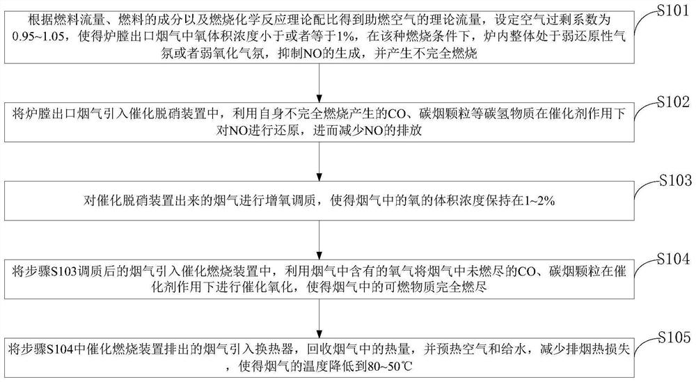
[0061]The invention implements nitrogen reduction and high-efficiency combustion step by step in the furnace and flue area. First, low nitrogen combustion is used in the furnace to control the formation of nitrogen oxides and high-concentration carbon monoxide under the condition of low air excess coefficient, and secondl...


PUM


Abstract

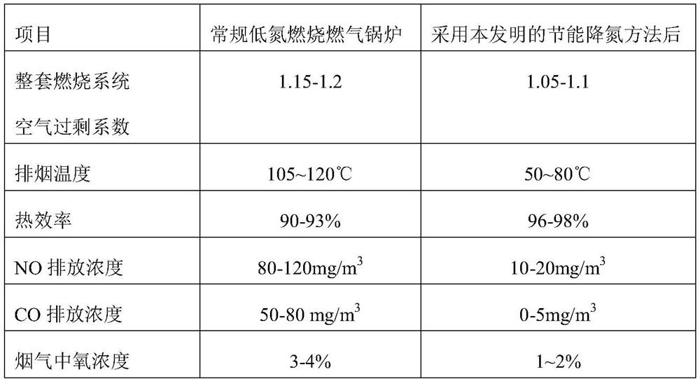
The invention belongs to the technical field of gas industrial boilers, and discloses a combustion method and system for achieving energy conservation and low nitrogen emission of a gas industrial boiler. The method comprises the following steps: firstly, controlling the generation of oxynitride and generating high-concentration carbon monoxide by adopting low-nitrogen combustion under the condition of a low coefficient of excess air in a furnace, and secondly, carrying out further catalytic reduction on nitrogen oxides in the flue gas in a flue region by utilizing incomplete combustion products such as carbon monoxide and soot particles in the flue gas as a reducing agent, and finally, incomplete combustion hydrocarbon substances remaining in the flue are eliminated in a catalytic combustion mode. A staged low-nitrogen combustion technology, a low-oxygen (low excess air coefficient) combustion technology, a hydrocarbon catalytic reduction denitration technology, a catalytic combustion technology and a deep flue gas waste heat recovery technology are organically combined, efficient combustion and low-nitrogen emission of the gas industrial boiler are achieved, meanwhile, the boiler efficiency is improved, and fuel consumption is reduced.

Description

technical field [0001] The invention belongs to the technical field of gas-fired industrial boilers, and in particular relates to a combustion method and system for realizing energy-saving and low-nitrogen emission of gas-fired industrial boilers. Background technique [0002] In recent years, with the advancement of coal-to-gas conversion in my country, the number of gas-fired industrial boilers has begun to increase, compared with coal-fired and oil-fired industrial boilers. Gas-fired industrial boilers have the advantages of simple structure, energy saving and environmental protection, and their particulate matter and sulfur dioxide emissions have been greatly reduced. However, the nitrogen oxides produced during the combustion of gas fuels such as natural gas and mixed gas cannot be ignored. Nitrogen oxides will cause serious pollution to air quality, lead to the generation of acid rain and acid fog, aggravate the greenhouse effect, destroy the ozone layer and produce ph...

Claims


Application Information

Patent Timeline
Patent Type & Authority Applications(China)
IPC IPC(8): F23J15/00F23J15/02F23J15/06F23G7/07
CPCF23J15/006F23J15/02F23J15/06F23G7/07F23J2215/10F23J2219/10Y02E20/30Y02E20/34
Inventor 刘豪黄璞涂垚杰徐顺塔张雄任豪金绍才仝宇航幸文婷
Owner HUAZHONG UNIV OF SCI & TECH
Why Eureka
Try Eureka