High-precision time difference type single-pulse ultrasonic flowmeter system and flow measurement method thereof

An ultrasonic and single-pulse technology, which is applied in the direction of measuring flow/mass flow, liquid/fluid solid measurement, measuring devices, etc., can solve the problems of complex system, increased number of devices, complex circuit, etc., and achieve simple and economical system, improve control accuracy, The effect of emitting large energy

Active Publication Date: 2012-10-24
BASIC INTELLIGENCE TECH
View PDF4 Cites 30 Cited by
  • Summary
  • Abstract
  • Description
  • Claims
  • Application Information

AI Technical Summary

Problems solved by technology

However, the energy of the multi-pulse transmitting circuit is not concentrated, the amplitude of the first wave of the received signal is small, the signal-to-noise ratio is poor, the receiving signal processing circuit is complex, and the cost is high; and when the ultrasonic wave is transmitted with a high-voltage narrow-band pulse signal, the transducer cannot completely convert the pulse signal. There is high-order resonance inside the energy, that is, it cannot completely convert and send out all the frequency components in the pulse signal, resulting in high-frequency resonance inside the transducer, which will cause interference when receiving signals, and can only be used for transmission or reception alone; The sound channel layout plan measures the forward and reverse time differe

Method used


Image

  • High-precision time difference type single-pulse ultrasonic flowmeter system and flow measurement method thereof
  • High-precision time difference type single-pulse ultrasonic flowmeter system and flow measurement method thereof
  • High-precision time difference type single-pulse ultrasonic flowmeter system and flow measurement method thereof

Examples


Embodiment Construction

[0038] In order to make the purpose, technical solutions and advantages of the present invention clearer, the implementation of the present invention will be further described in detail below in conjunction with the accompanying drawings:

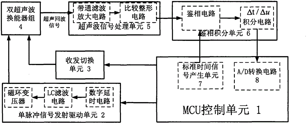
[0039] see figure 1 , based on the schematic diagram of the ultrasonic flowmeter system of the present invention, the system includes: MCU control unit 1, single pulse signal transmission drive unit 2, transceiver switching unit 3, ultrasonic transducer group 4, ultrasonic signal processing unit 5 and phase detection Integral Unit 6, the

[0040] The MCU control unit is used to send control signals to the transceiver switching unit and the single pulse signal transmitting drive unit, and

[0041] Send the standard delay signal to the phase detection and integration unit and use the measured forward travel time and reverse travel time of the ultrasonic wave to calculate the time difference between the reverse travel and forward travel of th...


PUM


Abstract

The invention discloses a high-precision time difference type single-pulse ultrasonic flowmeter system and a flow measurement method thereof. The method comprises the following steps of: sending a control signal to a transceiving switch unit and a single-pulse signal transmitting and driving unit; sending a standard time delay signal to a phase discrimination integral unit; calculating to obtain a time difference of the ultrasonic sequential stroke transmission and the ultrasonic return stroke transmission in a flowmeter pipeline by measured ultrasonic sequential stroke transmission time and the measured ultrasonic return stroke transmission time; selecting an ultrasonic energy converter; generating a single-period sine wave signal; sending the signal to the ultrasonic energy converter; sending an ultrasonic signal to an ultrasonic signal processing unit; filtering and amplifying the ultrasonic signal; determining an arrival signal by zero detection and threshold value detection; comparing the arrival signal with the standard time delay signal to obtain the ultrasonic sequential stroke transmission time and ultrasonic return stroke transmission time; and according to the time difference of the ultrasonic sequential stroke transmission and the ultrasonic return stroke transmission as well as the pipeline diameter, calculating to obtain the unit time flow of pipeline fluid.

Description

technical field [0001] The invention relates to the technical field of flow measurement equipment, in particular to a high-precision time-difference single-pulse ultrasonic flowmeter system and a method for measuring flow. Background technique [0002] Compared with mechanical and electromagnetic flow meters, ultrasonic flow meters have the advantages of strong adaptability to pipe diameter, large range ratio, no moving parts, non-contact measurement, zero pressure loss, and easy maintenance. Promising flow metering equipment, especially in recent years, has been widely used in heating heat metering. [0003] Ultrasonic flow measurement as a volume measurement method is mainly carried out through the following five steps: [0004] 1) The ultrasonic probe inside the pipeline emits sound waves in the fluid, starts the timing, and receives the ultrasonic signal after a certain period of time. [0005] 2) Perform preprocessing on the received ultrasonic signal, judge the arriv...

Claims


Application Information

Patent Timeline
IPC IPC(8): G01F1/66
Inventor 谭文胜
Owner BASIC INTELLIGENCE TECH
Why Eureka
Try Eureka