Built-in magnetic liquidometer

A liquid level gauge and magnetostrictive technology, applied in the field of industrial measurement, can solve the problems of loss of magnetic field strength due to high temperature resistance, affecting the measurement accuracy of the waveguide, and unsatisfactory shape design, so as to achieve timely and reliable measurement, ensure service life, and prevent jamming astringent effect

Active Publication Date: 2012-10-24
QINHUANGDAO HUADIAN MEASUREMENT & CONTROL EQUIP
View PDF4 Cites 2 Cited by
  • Summary
  • Abstract
  • Description
  • Claims
  • Application Information

AI Technical Summary

Problems solved by technology

Its disadvantages are: the magnetic part (6) is placed under high temperature conditions, and the high temperature degaussing characteristics of the magnetic part are extremely strict. Ordinary magnetic parts (6) are easy to demagnetize when working under high temperature conditions. Once the magnetic part (6) is demagnetized, the The entire measurement system completely loses the function of measuring the water level. Even if a high-temperature-resistant magnet is selected, its high-temperature resistance will lose its magnetic field strength, which will affect the measurement accuracy of the waveguide (7) and is prone to intermittent measurement signals, which poses a great safety hazard. Hidden danger: the shape design is not ideal, and the maintenance is inconvenient, especially when the magnetic part (6) is being repaired, the mouth door of the container (1) needs to be opened (this work can only be allowed when the outage is overhauled) to repair, the float (2) The connecting rod (3) between the magnetic part (6) and the magnetic part (6) is too long and there is no intermediate transition, which is extremely inconvenient for maintenance. If a large range is realized, it may lead to failure of maintenance

Method used


Image

  • Built-in magnetic liquidometer
  • Built-in magnetic liquidometer

Examples


Embodiment Construction

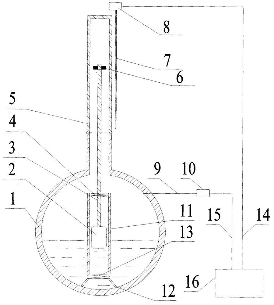
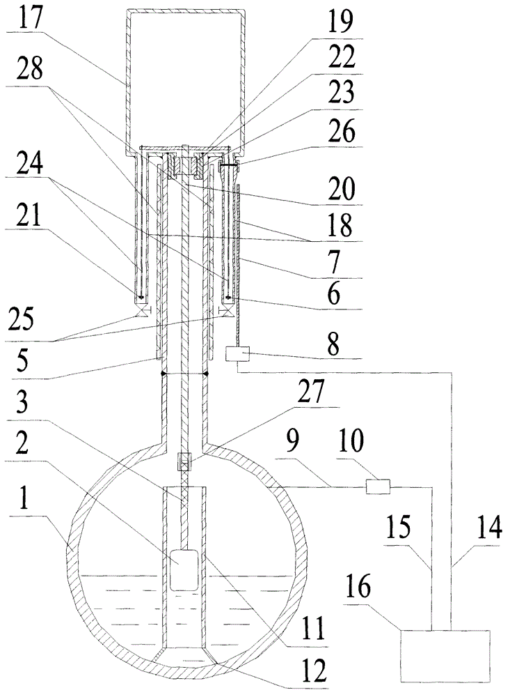
[0009] Such as figure 2 As shown, the protective sleeve (11) is fixedly installed in the container (1) through the mounting bracket (12); the float (2) is placed in the protective sleeve (11); the connecting rod (3) is welded on the float (2) The connecting rod (3) is connected with the upper connecting rod (20) through the casing (27); there are three holes at the bottom of the upper cylinder (17), and the holes on both sides are respectively connected with two cryogenic tubes (18) on the left and right, and the middle The hole is connected to the cylinder (5) connected to the container (1) by welding or flange connection. There are two connection methods. One is to connect according to the welding method of the low temperature pipe (18) on the left in the figure, and the other is to connect according to the welding method of the low temperature pipe (18) on the right. 18) Use the connection joint (26) to connect; the inner side of the upper part of the cylinder (5) is welde...


PUM


Abstract

The invention discloses a built-in magnetic liquidometer which is characterized in that a floater arranged in an actual liquid level in the container can directly measure the water level in the container, is a primary meter for measuring the water level in the container, and has accurate and reliable measurement results; a magnetic component driven by the floater is installed in a low-temperature tube under an upper barrel to reduce the high-temperature demagnetization, thereby enhancing the reliability of the measuring device; a transmission mechanism is connected in a sleeving mode, thereby being convenient to overhaul; and a corresponding density compensation calculation formula is utilized to compensate the measurement result, thereby reducing the measurement error and enhancing the measurement accuracy.

Description

technical field [0001] The invention relates to a built-in magnetic liquid level gauge, which is a water level measuring device for high-temperature and high-pressure containers. It belongs to the technical field of industrial measurement. Background technique [0002] The structure of the existing magnetic liquid level gauge installed in the water level of the steam drum used in the water level measurement of high temperature and high pressure vessels is as follows: figure 1 As shown, it consists of container (1), float (2), connecting rod (3), upper thrust spring (4), cylinder (5), magnetic component (6), waveguide (7), magnetotransmitter device (8), container pressure measuring instrument tube (9), container pressure transmitter (10), protective sleeve (11), mounting bracket (12), lower thrust spring (13), cable 1 (14), Cable 2 (15), secondary table (16) etc. are formed. The cylinder body (5) is welded on the top of the container (1) and communicated with the container...

Claims


Application Information

Patent Timeline
Patent Type & Authority Applications(China)
IPC IPC(8): G01F23/62
Inventor 崔明思
Owner QINHUANGDAO HUADIAN MEASUREMENT & CONTROL EQUIP
Why Eureka
Try Eureka