Thermoelectric conversion module and method of manufacturing thereof

A thermoelectric conversion and manufacturing method technology, applied in the manufacture/processing of thermoelectric devices, thermoelectric device components, thermoelectric devices that only use the Peltier or Seebeck effect, etc., can solve the problem of smaller temperature difference, lower power generation capacity, and low thermal conductivity and other issues to achieve the effect of high reliability and high power generation capacity

Inactive Publication Date: 2012-10-24
PANASONIC INTELLECTUAL PROPERTY MANAGEMENT CO LTD
View PDF22 Cites 8 Cited by
  • Summary
  • Abstract
  • Description
  • Claims
  • Application Information

AI Technical Summary

Problems solved by technology

[0031] However, Figure 8 In the conventional tubular thermoelectric conversion module shown above, since there is a polymer material layer or an adhesive resin with low thermal conductivity, the temperature difference between the ends of each thermoelectric conversion element becomes small, which is effective for power generation, and power generation The problem of reduced capacity
In addition, the length of the tubular thermoelectric conversion module is determined according to the width of the polymer material layer (substrate), so it is difficult to change the length of the tubular thermoelectric conversion module according to the size of the installation place of the tube as the heat source.
[0032] in addition, Figure 9 The above-mentioned conventional tubular thermoelectric conversion module has a problem that the diameter of the tube used as a heat source to install the tubular thermoelectric conversion module is limited because the insulating substrate is not flexible.
In addition, if there is a break in one place, it will not be able to generate electricity
[0033] Furthermore, a thermoelectric conversion module formed by electrically connecting a thermoelectric conversion element or a group of thermoelectric conversion elements with a flexible electrode member has insufficient reliability of the electrical connection of the thermoelectric conversion element or group of thermoelectric conversion elements when it is arranged on the surface of the tube. question

Method used


Image

  • Thermoelectric conversion module and method of manufacturing thereof
  • Thermoelectric conversion module and method of manufacturing thereof
  • Thermoelectric conversion module and method of manufacturing thereof

Examples


Embodiment approach 1

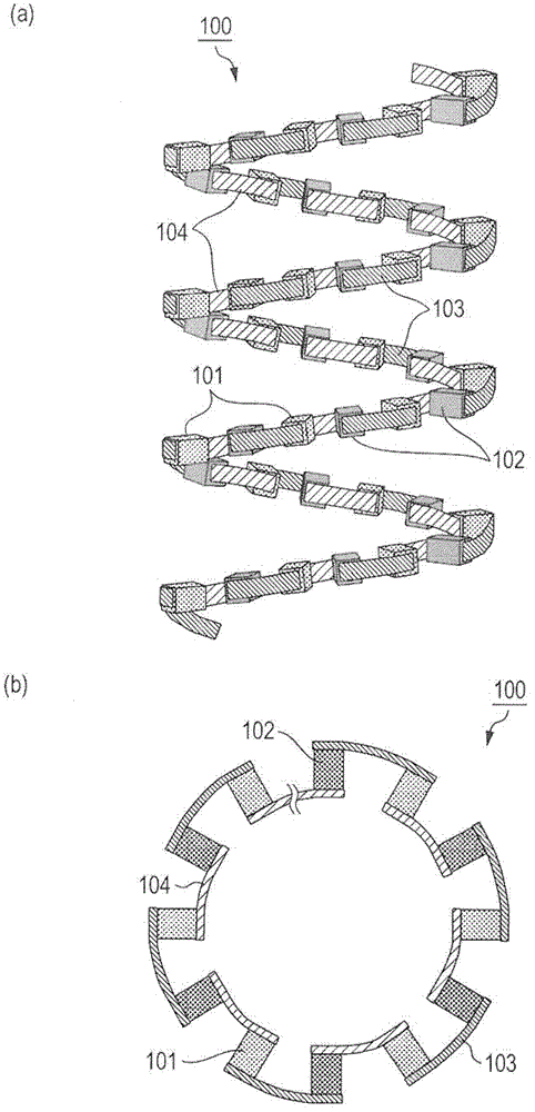
[0093] figure 1 is a schematic diagram of the thermoelectric conversion module 100 according to the first embodiment of the present invention. figure 1 (a) is a perspective view of the thermoelectric conversion module 100, figure 1 (b) is a top view of the thermoelectric conversion module 100 .

[0094] 1. The structure of the thermoelectric conversion module:

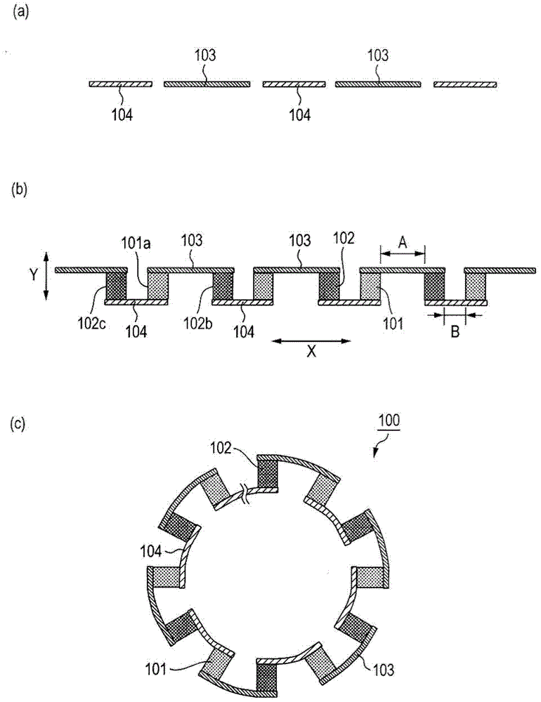
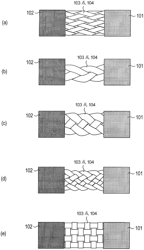
[0095] The thermoelectric conversion module 100 in this embodiment is basically composed of a P-type thermoelectric conversion element 101 , an N-type thermoelectric conversion element 102 , a braided wire 103 , and a braided wire 104 . The braided wire 103 corresponds to the braided wire A. The braided wire 104 corresponds to the braided wire B. Additionally, along the figure 1 P-type thermoelectric conversion elements 101 and N-type thermoelectric conversion elements 102 are alternately arranged sequentially in the circumferential direction of the spiral shape shown. At this time, if figure 1 As shown, on...

Embodiment approach 2

[0121] Next, a second embodiment of the present invention will be described with reference to the drawings.

[0122] Figure 5 It is a perspective view showing a schematic configuration of a thermoelectric conversion module 200 according to Embodiment 2 of the present invention. The thermoelectric conversion module 200 is basically composed of a P-type thermoelectric conversion element 101 , an N-type thermoelectric conversion element 102 , braided wires 103 , braided wires 104 , and electric wires 105 .

[0123] The adjacent P-type thermoelectric conversion elements 101 and N-type thermoelectric conversion elements 102 are electrically connected alternately and in series by braided wires 103 and braided wires 104 . Braided wire 103 is bonded to the upper surface of P-type thermoelectric conversion element 101 and the upper surface of N-type thermoelectric conversion element 102 . Braided wire 104 is bonded to the surface (lower surface) of P-type thermoelectric conversion e...


PUM


Abstract

The invention provides a thermoelectric conversion module, which can implement a high power generation capacity and high reliability of electric connection between thermoelectric conversion elements and meet various diameters and lengths of a tube as a heat source. The thermoelectric conversion module includes a straight-chain module unit. In the module unit, plural P-type elements and plural N-type elements, which are alternately arrayed, are electrically connected in series by a braided wire A and a braided wire B. The braided wire A connects one end surface of the P-type element and one end surface of the N-type element. The braided wire B connects the other end surface of the P-type element and the other end surface of the N-type element. The braided wire B is shorter than the braided wire A. The thermoelectric conversion module including only the module unit is spirally wound around a tube as a heat source.

Description

technical field [0001] The invention relates to a thermoelectric conversion module and a manufacturing method thereof. Background technique [0002] As a thermoelectric conversion element, an element utilizing the Peltier effect or the Seebeck effect is used. Since this thermoelectric conversion element has a simple structure, is easy to handle, and can maintain stable characteristics, its wide-ranging utilization has attracted attention in recent years. In particular, when used as an electronic cooling element, local cooling and precise temperature control around room temperature can be performed, so extensive research is being carried out for constant temperature of photovoltaics, semiconductor lasers, and the like. [0003] Such as Figure 7 As shown, the electronic cooling element or the thermoelectric module used for thermoelectric power generation is configured to connect the P-type thermoelectric conversion element 101 and the N-type thermoelectric conversion element...

Claims


Application Information

Patent Timeline
Patent Type & Authority Applications(China)
IPC IPC(8): H01L35/32H01L35/10H01L35/34
CPCH01L35/10H01L35/34H01L35/32H10N10/82H10N10/01H10N10/17
Inventor 丰田薰东田隆亮久保隆志
Owner PANASONIC INTELLECTUAL PROPERTY MANAGEMENT CO LTD
Why Eureka
Try Eureka