Self-adaptive constant-on-time control circuit

A constant on-time, control circuit technology, applied in control/regulating systems, electrical components, regulating electrical variables, etc., can solve problems such as operating frequency changes, achieve frequency concentration, improve efficiency, and reduce switching losses.

Inactive Publication Date: 2012-10-24
UNIV OF ELECTRONIC SCI & TECH OF CHINA
View PDF6 Cites 29 Cited by
  • Summary
  • Abstract
  • Description
  • Claims
  • Application Information

AI Technical Summary

Problems solved by technology

[0008] The purpose of the present invention is to solve the problem that the operating frequency of the switching regulator in

Method used


Image

  • Self-adaptive constant-on-time control circuit
  • Self-adaptive constant-on-time control circuit
  • Self-adaptive constant-on-time control circuit

Examples


Embodiment Construction

[0030] The present invention will be further described below in conjunction with the accompanying drawings and specific embodiments.

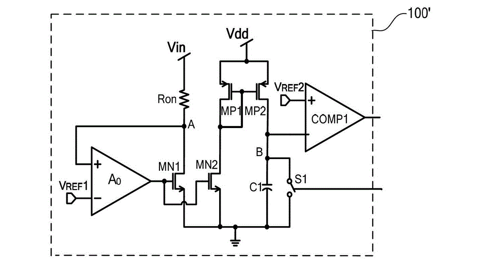
[0031] The structural diagram of the Adaptive constant on time (Acot) control circuit 100' in the embodiment of the present invention is as follows figure 2 As shown, it includes NMOS transistors MN1, MN2, PMOS transistors MP1, MP2, operational amplifier A0, comparator COMP1, capacitor C1, switch unit S1, and resistor Ron. Among them, NMOS transistor MN1, operational amplifier A0, and resistor Ron form a clamping position The op amp fixes the voltage at point A equal to VREF1. The specific connection relationship is that the inverting input terminal of the operational amplifier A0 is connected to the reference voltage VREF1, the gate of the NMOS transistor MN1 is connected to the output of A0, the source and substrate of MN1 are connected to the ground potential, and the drain of MN1 is connected to the high-gain A0. To the input terminal, no...


PUM


Abstract

The invention discloses a self-adaptive constant-on-time control circuit, which comprises a first transistor, a second transistor, a third transistor, a fourth transistor, a first operational amplifier, a first comparator, a first capacitive reactance unit, a first resistance unit and a switch unit. Due to the adoption of the self-adaptive constant-on-time control circuit, the problem of a traditional constant-on-time (Cot) control circuit that the working frequency is changed along with the input voltage can be solved, the quasi-steady working frequency under continuous conduction mode (CCM) status is realized, the on-off action of a power tube is reduced by reducing the working frequency under the discontinuous conduction mode (DCM) status, the on-off loss is reduced, the efficiency of a converter under a light load is improved, and the high efficiency of a full load section can be realized.

Description

technical field [0001] The invention belongs to the technical field of power supplies, and in particular relates to the design of a conduction time control circuit in a switching regulator. Background technique [0002] There are many control methods for switching regulators, the most common ones are voltage mode control and current mode control. These two control methods use the error amplifier EA to amplify the difference between the detected output voltage and the reference voltage to adjust the system. The duty cycle D in turn adjusts the output voltage. These two control methods need to add a compensation network to make the system work stably, especially for the current mode control. When the duty cycle D>0.5, an additional slope compensation circuit needs to be added to avoid sub-harmonic oscillation. The addition of these circuits increases the complexity of the control circuit, expands the area of ​​the control chip, and increases the overall cost; at the same t...

Claims


Application Information

Patent Timeline
IPC IPC(8): H02M3/158
Inventor 周泽坤黄建刚石跃代高强张竹贤谢海武明鑫张波
Owner UNIV OF ELECTRONIC SCI & TECH OF CHINA
Why Eureka
Try Eureka