Impedance matching circuit and impedance matching method of power amplifier

A technology of impedance matching circuit and power amplifier, which is applied in the direction of power amplifier, impedance matching network, amplifier input/output impedance improvement, etc., and can solve problems such as power amplifier distortion

Active Publication Date: 2012-10-24
HI TREND TECH SHANGHAI
View PDF2 Cites 7 Cited by
  • Summary
  • Abstract
  • Description
  • Claims
  • Application Information

AI Technical Summary

Problems solved by technology

[0008] The purpose of the present invention is to provide a power amplifier impedance matching circuit and impedance matching method based on power line carrier communication, which is used to solve the problems of distortion of the power amplifier caused by the impedance adaptation between the output of the power amplifier and the load of the power line.

Method used


Image

  • Impedance matching circuit and impedance matching method of power amplifier
  • Impedance matching circuit and impedance matching method of power amplifier
  • Impedance matching circuit and impedance matching method of power amplifier

Examples


example 1

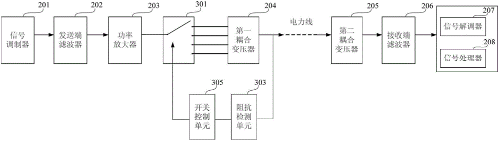
[0045] Example 1, assuming that the ideal load impedance of the power amplifier 203 is 8 ohms, if the impedance detection unit 303 detects that the current power line impedance is 2 ohms, the switch control unit 305 controls the switch 301 to switch to switch the coil of the first coupling transformer 204 The turns ratio is adjusted to N 1 :N 2 =2:1, then through the action of the first coupling transformer 204, the load impedance seen by the power amplifier 203 is 8 ohms (2*(N 1 / N 2 ) 2 =2*2 2 =8), to realize the mutual matching between the load impedance of the power line and the impedance of the power amplifier.

example 2

[0046] Example 2, assuming that the ideal load impedance of the power amplifier 203 is 8 ohms, if the impedance detection unit 303 detects that the current power line impedance is 16 ohms, the switch control unit 305 controls the switch 301 to switch to switch the coil of the first coupling transformer 204 The turns ratio is adjusted to Then, through the action of the first coupling transformer 204, the load impedance seen by the power amplifier 203 is 8 ohms The load impedance of the power line is matched with the impedance of the power amplifier.

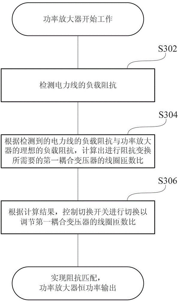
[0047] In summary, the present invention provides a power amplifier impedance matching circuit and impedance matching method based on power line carrier communication, which mainly lies in obtaining the load impedance of the power line by detecting the power line, and controlling the switching according to the ideal load impedance of the power amplifier. The switch switches the taps in the primary winding of the first coupling ...


PUM


Abstract

The invention provides an impedance matching circuit and an impedance matching method of a power amplifier based on power line carrier communication. The power line carrier communication comprises a signal modulator, a transmission end filter, the power amplifier and a first coupling transformer which are positioned at a transmission end and comprises a second coupling transformer, a receiving end filter, a signal modulator and a signal processor which are positioned at a receiving end. The impedance matching circuit of the power amplifier comprises a change-over switch, an impedance detecting unit and a switch control unit, wherein the impedance detecting unit is used for detecting load impedance of power lines, and the switch control unit is used for controlling changing-over of the change-over switch to adjust coil turn ratio of the first coupling transformer according to detecting results of the detecting unit so as to achieve mutual match of the load impedance of the power lines and impedance of the power amplifier. Compared with the prior art, the impedance matching circuit has the advantages of simple structure, convenience to control and the like.

Description

technical field [0001] The invention relates to a power amplifier in the field of power line carrier communication, in particular to a power amplifier impedance matching circuit and impedance matching method based on power line carrier communication. Background technique [0002] Power line carrier communication technology is a communication method that uses power lines as a communication medium to transmit data information. It uses carrier waves to realize the transmission and communication of data, voice, video, etc. Now this technology is widely used in communication, electric power, industrial control and other industries. This communication technology is an advanced technology in today's communication industry. [0003] Power line carrier communication technology generally includes: high-voltage power line carrier communication using a high-voltage transmission line with a voltage level of 35kV and above as a communication medium; medium-voltage power line carrier commu...

Claims


Application Information

Patent Timeline
Patent Type & Authority Applications(China)
IPC IPC(8): H03F1/56H03F3/20H03H11/28
Inventor 刘飞何巍荀本鹏马侠
Owner HI TREND TECH SHANGHAI
Why Eureka
Try Eureka