Method and arrangement for controlling a wind turbine

a technology of wind turbine and control arrangement, which is applied in the direction of wind energy generation, mechanical equipment, machines/engines, etc., can solve the problems of very likely conservative target values, and achieve the effects of reducing power generation, increasing power output, and increasing power outpu

Active Publication Date: 2017-04-04
SIEMENS GAMESA RENEWABLE ENERGY AS
View PDF18 Cites 5 Cited by
  • Summary
  • Abstract
  • Description
  • Claims
  • Application Information

AI Technical Summary

Benefits of technology

[0017]Operating the rotor according to the second rotational speed reference may be performed before or after operating the rotor according to the first rotational speed reference. In particular, while operating the rotor according to the first rotational speed reference and / or while operating the rotor according to the second rotational speed reference, the blade pitch angle may be kept constant or may be changed, in particular in dependence of a wind speed, in order to maintain a constant power output. In particular, when the wind speed increases, and while the rotor is operated according to the first rotational speed reference, the blade pitch angle may have been increased (in order to maintain a constant power output while the wind speed is increasing). Thereby, the blade pitch angle may have been increased to lie above a blade pitch angle threshold. If the blade pitch angle of the rotor blade has been increased above the blade pitch angle threshold, the rotor may then switch from operating the rotor according to the first rotational speed reference to operating the rotor according to the second rotational speed reference. Thereby, operation of the rotor at a rotational speed higher than when operating the rotor according to the first rotational speed reference may be achieved. Thereby, the possibility is provided to also increase power output of the wind turbine. Thereby, the efficiency of the wind turbine, in particular regarding power output, may be increased.
[0052]Monitoring the at least one electrical component may include performing one or more measurements using one or more sensors, such as a temperature sensor, a current sensor, a voltage sensor, a cooling fluid flow sensor, etc. In particular, the at least one electrical component may be required to be operated according to limited operational conditions, which may limit in particular temperature, current, voltage, etc. If the monitoring yields, that the electrical component is being operated well within margins of their operational limiting conditions, the power output of the wind turbine may be increased. In particular, power output may be increased depending on how close the electrical component approached its operational limits. Thereby, energy output of the wind turbine may be improved.

Problems solved by technology

The inventors found that in conventional systems, where the target rotational speed and / or target power are fixed, these target values are very likely to be too conservative, since they have to consider worst-case wind speeds, turbulence, wind shear, ambient temperature, etc.

Method used


Image

  • Method and arrangement for controlling a wind turbine
  • Method and arrangement for controlling a wind turbine
  • Method and arrangement for controlling a wind turbine

Examples


Embodiment Construction

[0063]The illustration in the drawings is in schematic form. It is noted that in different figures, similar or identical elements are provided with the same reference signs or with reference signs, which are different from the corresponding reference signs only within the first digit.

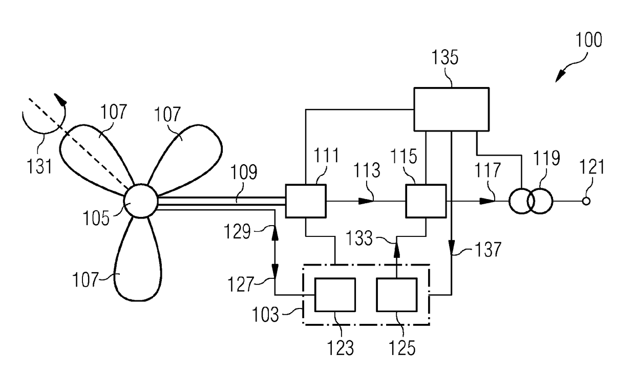
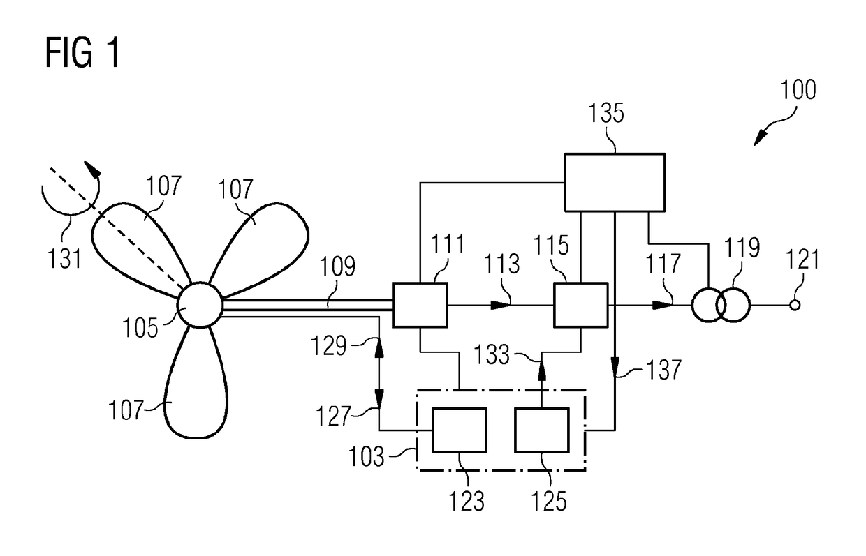
[0064]FIG. 1 schematically illustrates a wind turbine 100 including an arrangement 103 for controlling the wind turbine according to an embodiment of the present invention. The wind turbine includes a hub 105 at which plural rotor blades 107 are connected, wherein the hub is supported within a not illustrated nacelle which is mounted on top of a wind turbine tower. The wind turbine blades 107 are mechanically fixed to a rotation shaft 109 which rotates upon impact of wind onto the wind turbine blades 107. The rotating shaft 109 drives a generator 111 which provides an electrical output stream 113 to a AC-DC-AC converter 115 which converts the variable frequency output stream 113 to a fixed frequency out...


PUM


Abstract

A method of controlling a wind turbine having a rotor to which at least one rotor blade is connected, is provided herein. The method includes operating the rotor according to a first rotational speed reference; and operating the rotor according to a second rotational speed reference above the first rotational speed reference, if a fluctuation of an actual rotational speed of the rotor decreases below a fluctuation threshold and / or if a blade pitch angle of the rotor blade increases above a blade pitch angle threshold. The method may further include wherein the rotor is operated according to the first rotational speed reference, if the fluctuation of an actual rotational speed of the rotor increases above another fluctuation threshold which is above the fluctuation threshold and / or if the blade pitch angle of the rotor blade decreases below another blade pitch angle threshold which is below the blade pitch angle threshold.

Description

CROSS REFERENCE TO RELATED APPLICATIONS[0001]This application is the US National Stage of International Application No. PCT / EP2013 / 055894 filed Mar. 21, 2013, and claims the benefit thereof. The International Application claims the benefit of European Application No. EP12186571 filed Sep. 28, 2012. All of the applications are incorporated by reference herein in their entirety.FIELD OF INVENTION[0002]The present invention relates to a method and to an arrangement for controlling a wind turbine, in order in increase power production efficiency.ART BACKGROUND[0003]Conventionally, a wind turbine may be operated using a fixed or constant target rotational speed (also referred to as reference rotational speed or rotational speed set-point) and a fixed target power (also referred to as a reference power or a power set-point). In these conventional systems, a turbine controller may aim to hold this fixed target rotational speed and fixed target power at high wind speeds. In this case, there...

Claims


Application Information

Patent Timeline
Patent Type & Authority Patents(United States)
IPC IPC(8): F03D7/02F03D9/00F03D7/04
CPCF03D7/0276F03D7/028F03D7/0224F03D7/0296F03D7/042F03D9/25F05B2270/101F05B2270/107F05B2270/1033F05B2270/20F05B2270/327F05B2270/335Y02E10/723Y02E10/72F03D9/255
Inventor ESBENSEN, THOMASKRISHNA, RAMAKRISHNAN
Owner SIEMENS GAMESA RENEWABLE ENERGY AS
Why Eureka
Try Eureka