
Cordless telephone switchboard for group

A cordless telephone and exchange technology, applied in the field of exchange, can solve problems such as complex line installation, difficult network troubleshooting, weak system scalability, etc., and achieve high-fidelity voice transmission and simple structure

Inactive Publication Date: 2012-10-24
HARBIN INST OF TECH
View PDF3 Cites 1 Cited by
  • Summary
  • Abstract
  • Description
  • Claims
  • Application Information

AI Technical Summary

Problems solved by technology

[0003] The purpose of the present invention is to solve the problem of complex line erection, difficult network troubleshooting, and the inability to communicate between slaves of existing wireless switches and weak system scalability in the use of traditional wired telephone exchanges. disadvantages, thus presenting a group cordless telephone exchange

Method used

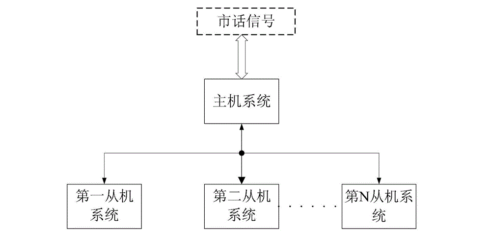

Image

  • Cordless telephone switchboard for group
  • Cordless telephone switchboard for group
  • Cordless telephone switchboard for group

Examples


specific Embodiment approach 1

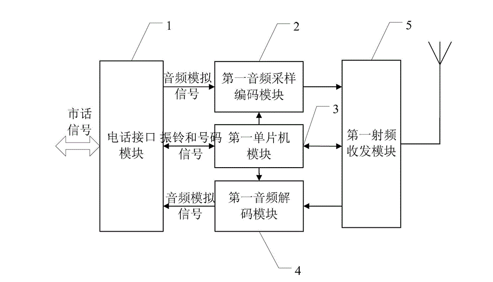
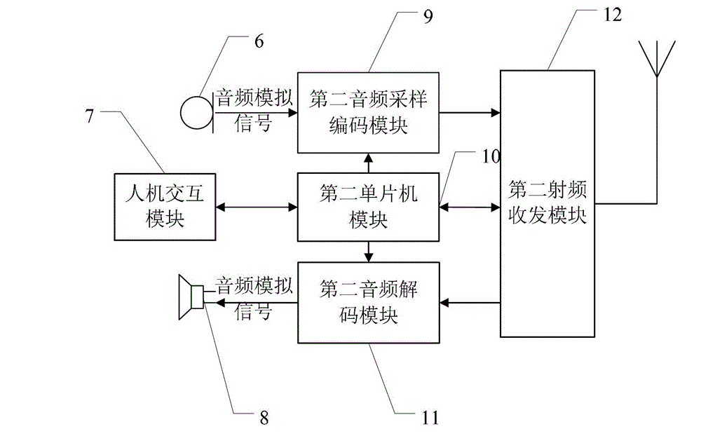
[0034] Specific implementation mode 1. Combination figure 1 , figure 2 with image 3 Specifically illustrate this embodiment, the group cordless telephone exchange described in this embodiment, it comprises a master system and N slave systems, N is greater than or equal to two,

[0035] The host system includes a telephone interface module 1, a first audio sampling encoding module 2, a first single-chip microcomputer module 3, a first audio decoding module 4 and a first radio frequency transceiver module 5,

[0036] The slave system includes a microphone 6, a human-computer interaction module 7, a loudspeaker 8, a second audio sampling encoding module 9, a second single-chip microcomputer module 10, a second audio decoding module 11 and a second radio frequency transceiver module 12,

[0037] The local call signal is input to the local call signal input end of the telephone interface module 1,

[0038] The telephone interface module 1 separates the ring signal, number sign...

specific Embodiment approach 2

[0057] Embodiment 2. The difference between this embodiment and the group cordless telephone exchange described in Embodiment 1 is that the telephone interface module 1 used in the host system is an analog telephone interface chip PH8810, which adopts electronic coupling technology.

specific Embodiment approach 3

[0058] Specific Embodiment 3. The difference between this embodiment and the group cordless telephone exchange described in Specific Embodiment 1 is that the first audio sampling encoding module 2 adopted by the master system is of the same type as the second audio sampling encoding module 9 adopted by the slave system. , are WM8738 chips.


PUM


Abstract

The invention discloses a cordless telephone switchboard for a group and relates to the cordless telephone switchboard for the group. In order to solve the defects that the traditional wired telephone switchboard has a complicated line, a network fault is maintained difficultly, communication from the existing wireless switchboard to the switchboard cannot be carried out, and the expandability is weak, when an external phone call is coming, a ring, a number and an analogue audio output signal are separated out from a local call signal through a host computer system telephone interface module; the ring signal and the number signal are transmitted to a single chip module to process; an audio signal is converted into a digital signal to be transmitted to the single chip module for processing through an audio sampling encoding module; the single chip module transmits the signal to the host computer system radio transceiver module; the host computer communicates with a slave computer through a radio module; and a slave computer system single chip module transmits a digital audio signal to an audio decoding module, converts the digital audio signal into an analogue audio signal, and transmits the analogue audio signal to a telephone interface module through the radio transceiver module to achieve multi-user transmission. The cordless telephone switchboard for the group disclosed by the invention is suitable for the field of communication.

Description

technical field [0001] The invention relates to an exchange, in particular to a group cordless telephone exchange. Background technique [0002] At present, digital voice switching technology is mainly used in group telephone exchanges. The PBX is composed of outside lines and extensions. It consists of several telephones sharing one or more outside lines, used for small and medium-sized businesses, and can also be used for residential and secretary telephones. When an outside line calls in, it can be answered by any phone, and can be transferred to the desired called party. Group telephone exchange technology is a common means of communication management in modern offices, enabling telephone administrators to collectively manage incoming outside calls and outgoing inside calls. In recent years, with the development of our country's economy, the output of communication equipment including PBX has increased significantly. With the wide application of switch technology, my...

Claims


Application Information

Patent Timeline
IPC IPC(8): H04M3/00
Inventor 任广辉吴迪刘利欢张莉杨芳芳
Owner HARBIN INST OF TECH
Learn More