Method, device and transmission system for transmitting and receiving data block

A data block and sender technology, applied in network traffic/resource management, electrical components, wireless communication, etc., can solve problems that cannot meet the needs of a large number of terminal access

Active Publication Date: 2012-10-24
HONOR DEVICE CO LTD
View PDF3 Cites 11 Cited by
  • Summary
  • Abstract
  • Description
  • Claims
  • Application Information

AI Technical Summary

Problems solved by technology

It can be seen that in the prior art, since both TFI and USF have limited lengths, only a limited nu

Method used


Image

  • Method, device and transmission system for transmitting and receiving data block
  • Method, device and transmission system for transmitting and receiving data block
  • Method, device and transmission system for transmitting and receiving data block

Examples


Embodiment 1

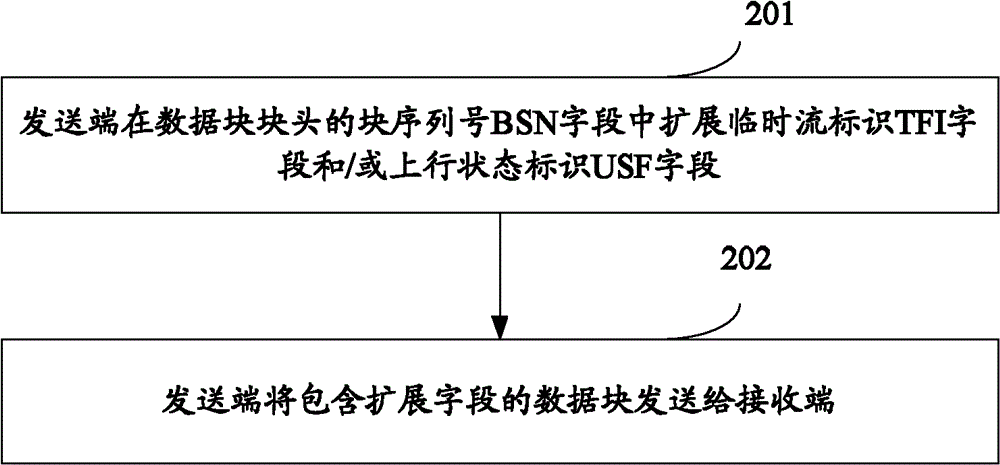
[0037] see figure 2 , which is a flowchart of an embodiment of a method for sending a data block in the present invention, including the following steps:

[0038] Step 201: The sending end extends the temporary flow identifier TFI field and / or the uplink state identifier USF field in the block sequence number BSN field of the data block header;

[0039] Wherein, the sending end expands the TFI field and / or the uplink status identifier USF field in the BSN field of the data block header includes: the sending end extends the temporary flow identifier TFI field in the block sequence number BSN field of the uplink data block header; the sending end Extend the TFI field and / or the uplink status identifier USF field in the BSN field of the block header of the downlink data block.

[0040] Step 202: the sending end sends the data block including the extension field to the receiving end.

[0041] It can be seen from the above embodiments that at the sending end, one or several bits...

Embodiment 2

[0043] see image 3 , which is a flow chart of another embodiment of a method for sending a data block in the present invention. In this embodiment, the terminal acts as a sending end to extend the TFI field in the BSN field of the block header of the uplink data block. The method includes the following steps:

[0044] Step 301: The terminal extends the temporary flow identifier TFI field in the block sequence number BSN field of the uplink data block header;

[0045] For example, if there is only one BSN1 field in the uplink RLC / MAC data block header, one or more bits can be used in the BSN1 field to extend the TFI field, see Pic 4-1 , Pic 4-1 It is a schematic structural diagram of extending the TFI field in a BSN field of the uplink RLC / MAC data block header in the present invention,

[0046] For another example, there are two BSN fields BSN1 and BSN2 in the RLC / MAC data block header, and one or more bits can be used in the BSN1 and BSN2 fields to extend the TFI field, ...

Embodiment 3

[0052] see Figure 5 , which is a flow chart of another embodiment of a method for sending a data block in the present invention. In this embodiment, the base station, as the sending end, extends the TFI field and / or the uplink state identifier USF in the BSN field of the block header of the downlink data block field, the method includes the following steps:

[0053] Step 501: the base station extends the TFI field and / or the uplink state identifier USF field in the BSN field of the downlink data block header;

[0054] Since the field to be extended in the downlink data block header may be the TFI field or the USF field, or the TFI field and the USF field may be extended simultaneously, therefore, the TFI field and / or the USF field may be extended in the BSN field.

[0055] Among them, in addition to the following Pic 4-1 and 4-2 In addition to the extended TFI field of the structure, you can also follow the Figure 6-1 In the manner shown, one or more extended USF fields...


PUM


Abstract

An embodiment of the invention discloses a method, a device and a transmission system for transmitting and receiving a data block. At a transmitting terminal, the transmitting terminal extends a temporary flow identity (TFI) field and/or an uplink state flag (USF) field in a block sequence number (BSN) field of a data block header, and transmits the data block which comprises the extension field to a receiving terminal. Correspondingly, at the receiving terminal, the receiving terminal receives the data block, analyzes the data block, obtains the TFI field and/or the USF field from the BSN field of the data block header, combines an extension bit of the TFI field obtained through analysis with a data bit of the TFI field in the data block header so as to obtains an extended TFI value, and combines an extension bit of the USF field with a data bit of the USF field in the data block header so as to obtain an extended USF value. According to the embodiment of the invention, requirements of a large number of terminal accesses can be met.

Description

technical field [0001] The present invention relates to the field of wireless communication, in particular to a method, device and transmission system for sending and receiving data blocks. Background technique [0002] M2M (Machine to Machine) communication refers to network communication between one or more network elements without human participation. For example, applications such as traffic control and management, factory monitoring, and remote meter reading all utilize M2M communications. According to preliminary estimates, terminals used for person-to-person communication may only account for 1 / 3 of the entire terminal market in the future, while a larger amount of communication belongs to M2M communication. [0003] In the M2M communication implemented by GSM (Global System for Mobile communications, Global System for Mobile Communications), service data on the application layer will be divided or combined into RLC / MAC data blocks, and transmitted on the air interfa...

Claims


Application Information

Patent Timeline
IPC IPC(8): H04W28/06
CPCH04W28/06H04W72/1278H04W72/20
Inventor 房明余勇军王济勇舒兵
Owner HONOR DEVICE CO LTD
Why Eureka
Try Eureka