Method for manufacturing electronic equipment

A technology of electronic equipment and manufacturing method, applied in the direction of electrical components, electrical components, etc., can solve problems such as increased production costs, ineffective protection of components, and inability to meet the high protection requirements of electronic equipment, so as to make up for cracks, The effect of eliminating dead angle and effective protection

Active Publication Date: 2015-05-27
SHENZHEN INVT ELECTRIC
View PDF6 Cites 0 Cited by
  • Summary
  • Abstract
  • Description
  • Claims
  • Application Information

AI Technical Summary

Problems solved by technology

[0003] At present, in order to improve the protection ability of electronic equipment to adapt to the harsh environment, the generally adopted method in the industry is to comprehensively upgrade the IP level of electronic equipment through structural improvement or to spray the entire electronic equipment with a single conformal paint. However, the above two Both methods have certain defects. The former will greatly increase the production cost, while the latter, due to the structural limitations of electronic equipment, when spraying the conformal paint on the whole machine, due to the blocking effect of various copper bars, structural parts, devices, etc. It cannot be sprayed evenly and effectively to the internal space, and the main parts to be protected cannot be effectively treated
Moreover, the conformal paint protective layer produced by a single spraying of the conformal paint is prone to cracks, and the components inside the electronic equipment cannot be effectively protected. Therefore, the electronic equipment manufactured in this way cannot meet the requirements of dusty, high humidity and High protection requirements for electronic equipment in harsh environments such as high corrosive pollution

Method used


Image

  • Method for manufacturing electronic equipment
  • Method for manufacturing electronic equipment
  • Method for manufacturing electronic equipment

Examples


Embodiment Construction

[0024] The technical solutions in the embodiments of the present invention will be clearly and completely described below in conjunction with the drawings in the embodiments of the present invention, and similar component numbers in the drawings represent similar components. Apparently, the embodiments described below are only a part of the embodiments of the present invention, rather than all the embodiments. Based on the embodiments of the present invention, all other embodiments obtained by persons of ordinary skill in the art without creative efforts fall within the protection scope of the present invention.

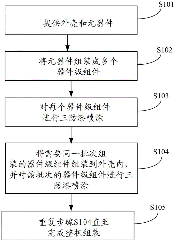
[0025] The electronic device manufacturing method of the present invention can be used to manufacture electronic devices of various types. The electronic device manufacturing method of the present invention will be described in detail below by taking three different types of electronic devices as examples.

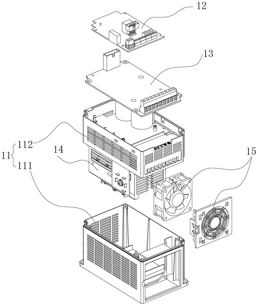
[0026] figure 1 and figure 2 A first embodiment of the m...


PUM


Abstract

The invention discloses a method for manufacturing electronic equipment. The method comprises the following steps of: providing parts to be assembled into the electronic equipment, wherein the parts comprise components and a shell; assembling the components into a plurality of modules; performing conformal coating spraying on each module; assembling the sprayed modules in the shell; and performing conformal coating spraying on the modules in the shell. The method for manufacturing the electronic equipment has the advantages that the components are modularized and then individually sprayed, the components are sprayed repeatedly in the overall assembly process, and the components of the electronic equipment can be comprehensively protected by multilayer spraying which comprises individual spraying and overall spraying, so the whole protection performance of the electronic equipment is effectively improved; and on the premise that the international protection (IP) grade is not improved, the operation reliability of the electronic equipment in service environment such as high dust content, high humidity and high corrosive pollution can be improved.

Description

technical field [0001] The present invention relates to the technical field of electronic equipment, in particular to a manufacturing method of electronic equipment. Background technique [0002] With the development of information technology, electronic equipment such as frequency converters are more and more widely used in various industries. When electronic equipment is used in industries with serious environmental pollution such as ceramic manufacturing, printing and dyeing pumps, and chemical industry, due to the characteristics of the working environment such as dusty, high humidity, and high corrosive pollution, if the protection ability of electronic equipment is insufficient, the harsh The environment will seriously damage the stability and reliability of electronic equipment. Therefore, the industry has put forward higher requirements for the protection ability of electronic equipment. [0003] At present, in order to improve the protection ability of electronic e...

Claims


Application Information

Patent Timeline
Patent Type & Authority Patents(China)
IPC IPC(8): H05K13/00
Inventor 刘志勇滕建新殷江洪
Owner SHENZHEN INVT ELECTRIC
Why Eureka
Try Eureka