Electromagnetic flow control valve and high pressure fuel supply pump using same

A technology of flow control valve and high-pressure fuel, which is applied to fuel injection pumps, fuel injection devices, special fuel injection devices, etc., and can solve problems such as the cross-sectional area of ​​difficult fuel passages

Inactive Publication Date: 2012-10-24
HITACHI AUTOMOTIVE SYST LTD
View PDF9 Cites 13 Cited by
  • Summary
  • Abstract
  • Description
  • Claims
  • Application Information

AI Technical Summary

Problems solved by technology

However, in order to provide a hole in the armature, there are restrictions on the arrangement of the spring and the rod passing through the center, etc., and it is difficult to ensure a sufficient cross-sectional area of ​​the fuel passage through the through hole.

Method used


Image

  • Electromagnetic flow control valve and high pressure fuel supply pump using same
  • Electromagnetic flow control valve and high pressure fuel supply pump using same
  • Electromagnetic flow control valve and high pressure fuel supply pump using same

Examples


Embodiment 1

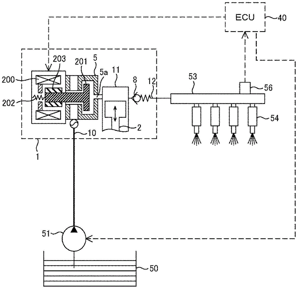
[0029] figure 1 An overall configuration of a system using a normally-open solenoid valve implementing Embodiment 1 and Embodiment 2 of the present invention is shown. A portion surrounded by a dotted line represents a pump housing 1 of the high-pressure fuel supply pump, and the mechanisms and components shown in the dotted line are integrated therein. A suction port 10 , a pressurization chamber 11 , and a fuel discharge passage 12 are formed in the pump housing 1 . An electromagnetic valve 5 and a discharge valve 8 are provided in the suction port 10 and the discharge passage 12, and the discharge valve 8 constitutes a check valve for restricting the flow direction of fuel. In addition, between the suction port 10 and the pressurized chamber 11 , the solenoid valve 5 is held by the pump casing 1 and a solenoid coil 200 , an armature 203 , and a spring 202 are disposed. A force is applied to the valve core 201 through the spring 202 in the direction of valve opening. As a...

Embodiment 2

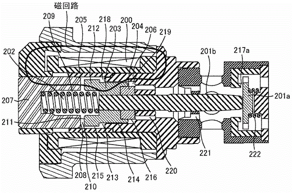
[0048] image 3 A cross section of the solenoid valve according to the second embodiment of the present invention when the valve is opened is shown. The shape of the valve body 201 is different from Example 1, and it is divided into two members of the valve body part 201a and the rod part 201b in this Example. The rod portion 201b bears the force exerted by the spring 202 along the valve opening direction, and the stroke is limited by the contact of the stopper 204 with the inside of the solenoid valve. On the other hand, the spool portion 201a receives an urging force in the valve closing direction from the spool spring 222, and presses against the front end of the rod portion 201b. Here, the urging force of the spring 202 is set to be greater than the urging force of the spool spring 222, and when the electromagnetic coil 200 is OFF, the valve plate 217a and the spool portion 201a are kept in the open state without contact. When the pump is in the compression process, if t...

Embodiment 3

[0051] Figure 4 The whole structure of the system of the normally closed electromagnetic valve which implements Example 3 and Example 4 of this invention is shown. The normally closed mode is the opposite of the normally open mode. It is a solenoid valve mode in which the state of the solenoid coil is OFF and the valve is closed, and the state of the solenoid coil is ON to form the valve open state. and figure 1 The arrangement of components inside the solenoid valve 30 is different from that shown in the normally open mode. An electromagnetic coil 300 , an armature 303 , and a spring 302 are arranged inside the electromagnetic valve 30 . A force is applied to the valve core 301 in the direction of closing the valve through the spring 302 . Accordingly, when the electromagnetic coil 300 is OFF, the valve element 301 is in a closed state. The injector 54 and the pressure sensor 56 are attached to the common rail 53 as in the case of the normally open system. The injector ...


PUM


Abstract

Disclosed is a highly responsive and high power electromagnetically actuated flow control valve of compact and simple construction, and a high pressure fuel supply pump equipped with same. The valve is comprised of: a flange part forming a suction surface on an anchor; a first circumferential part with a diameter smaller than that of the flange part; a cylindrical non-magnetic region surrounding and facing an outer surface of the flange part and a third opening; and a first fluid gathering part constructed so as to communicate with a back pressure chamber via the third opening. According to this construction, if the diameter of the flange part is expanded so as to expand the cross-section of the suction surface, the amount of fuel pushing the anchor aside increases accordingly, but as part of the fuel is absorbed by the first fluid gathering part the amount of fuel passing through the fuel passage is not increased compared to before the diameter of the flange was expanded. Thus, as the cross-section of the suction surface can be expanded without expanding the fuel passage, there is no increase in magnetic resistance arising from the fuel passage and suction force is increased effectively.

Description

technical field [0001] The present invention relates to an electromagnetic flow rate control valve used, for example, in a high-pressure fuel supply pump or the like that supplies fuel to an engine at high pressure. Background technique [0002] Conventionally, as an electromagnetic flow control valve of a high-pressure fuel supply pump, various methods have been proposed that employ a normally open electromagnetic valve that is in an open state when no power is applied. For example, Japanese Patent Application Laid-Open No. 2002-48033 discloses a technique of providing a through hole in an armature (mover) having a magnetic attraction surface to reduce fluid resistance and achieve high responsiveness. In addition, in Japanese Patent Application Laid-Open No. 2004-125117, Japanese Patent Laid-Open No. 2004-128317, etc., it is described that in a normally closed solenoid valve, a through hole is provided in the center of the armature (movable member) having a magnetic attract...

Claims


Application Information

Patent Timeline
Patent Type & Authority Applications(China)
IPC IPC(8): F02M59/36F02M51/00
CPCF02M2200/502F02M59/366F02M59/466F02M2200/9069F02M59/368Y10T137/7761
Inventor 有富俊亮德尾健一郎菅波正幸栋方明广臼井悟史
Owner HITACHI AUTOMOTIVE SYST LTD
Why Eureka
Try Eureka