Chamfering blade with staggered teeth

A technology of staggered teeth and chamfering, applied to gear teeth, components with teeth, gear tooth manufacturing tools, etc., can solve problems such as single function, less open chamfering tools, and no chamfering

Inactive Publication Date: 2012-10-31
上海星合机电有限公司
View PDF8 Cites 5 Cited by
  • Summary
  • Abstract
  • Description
  • Claims
  • Application Information

AI Technical Summary

Problems solved by technology

[0002] The existing chamfering cutter is simple in design and manufacture, and has a single function. When the side of the gear is a step, it can only process a part of the step, and cannot perform chamfering on the entire end surface profile. If it is to be integrated into an assembly with conventional technology, the structure is complicated. bulky
If the steps are processed separately, the processing time will be doubled, and the positioning will be repeated, and the secondary processing will result in poor accuracy and processing quality.
[0003] In the known technologies, especially the chamfering tools and technologies in the patent application documents are less disclosed

Method used


Image

  • Chamfering blade with staggered teeth
  • Chamfering blade with staggered teeth
  • Chamfering blade with staggered teeth

Examples


Embodiment Construction

[0014] Further illustrate by the following examples.

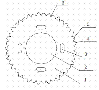
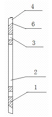
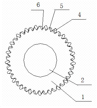
[0015] The cutter body 1 is circular, and there is a shaft hole 2 in the middle of the cutter body 1, and waist-shaped grooves 3 are evenly distributed around the shaft hole 2. 5 with alveolar 6.

[0016] The cutter teeth 4 and the staggered teeth 5 have different shapes, or different heights, or different thicknesses, or different phases, or different axial positions.

[0017] In the present invention, the tool is a complete single blade part, but multi-functional chamfering is realized on the same chamfering knife, and one set of cutter teeth 4 is combined with more than one set of staggered teeth 5, that is, there are 2 sets or 2 sets on the outer circle For the above different combinations of cutter teeth 4 and offset teeth 5, the arrangement of cutter teeth 4 and offset teeth 5 is mutually staggered, and the design of each set of teeth needs to realize its own function, corresponding to a specific function re...


PUM


Abstract

A chamfering blade with staggered teeth adopts the structure that the blade body (1) is circular; a shaft hole (2) is formed in the middle of the blade body (1); waisted grooves (3) are uniformly distributed on the circumference of the shaft hole (2); blade teeth (4) and staggering teeth (5), which are different from each other in shape, are formed on the outer edge of the blade body (1) in a staggered manner; and a tooth groove (6) is formed between each blade tooth and an adjacent staggering tooth. As an integral single blade adopts the tooth staggered structure, that is, the blade teeth (4) and the staggering teeth (5), which are different from each other in size, are formed on the outer edge of the blade body, multi-purpose processing can be conducted on the end surface of a gear through one-time processing, and multifunctional chamfering can be realized with one chamfering blade.

Description

technical field [0001] The invention relates to a tool for international patent classification B23B turning, boring or B24D grinding, polishing or sharpening, and belongs to the technical field of gear end face chamfering, in particular to a staggered tooth chamfering knife. Background technique [0002] The existing chamfering cutter is simple in design and manufacture, and has a single function. When the side of the gear is a step, it can only process a part of the step, and cannot perform chamfering on the entire end surface profile. If it is to be integrated into an assembly with conventional technology, the structure is complicated. bulky. If the steps are processed separately, the processing time will be doubled, and the positioning will be repeated, and the secondary processing will result in poor precision and processing quality. [0003] In the known technologies, especially the chamfering tools and technologies in the patent application documents are less disclos...

Claims


Application Information

Patent Timeline
Patent Type & Authority Applications(China)
IPC IPC(8): B23F21/00
Inventor 蒋能
Owner 上海星合机电有限公司
Why Eureka
Try Eureka