
Primary current signal simulator for optical current transformer

A technology of current transformer and current signal, applied in the field of primary current signal simulator, can solve the problems of large primary current and difficult research and development process of optical current transformer, etc.

Inactive Publication Date: 2012-10-31
BEIJING DERUN CENTURY TECH
View PDF7 Cites 4 Cited by
  • Summary
  • Abstract
  • Description
  • Claims
  • Application Information

AI Technical Summary

Problems solved by technology

[0005] In the prior art, the optical current transformer based on this principle directly measures the primary current, but in the general power system, the primary current is relatively large, ranging from hundreds of amps to tens of thousands of amps, which makes the research and development process of the optical current transformer difficult. caused great difficulty

Method used


Image

  • Primary current signal simulator for optical current transformer
  • Primary current signal simulator for optical current transformer
  • Primary current signal simulator for optical current transformer

Examples


Embodiment Construction

[0023] Hereinafter, embodiments of the present invention will be described with reference to the drawings.

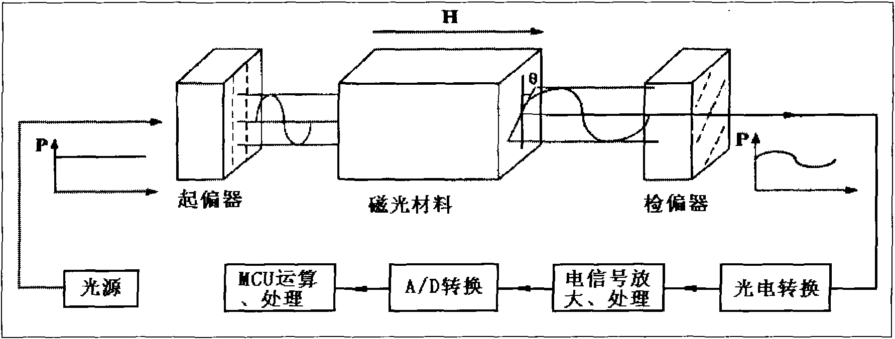
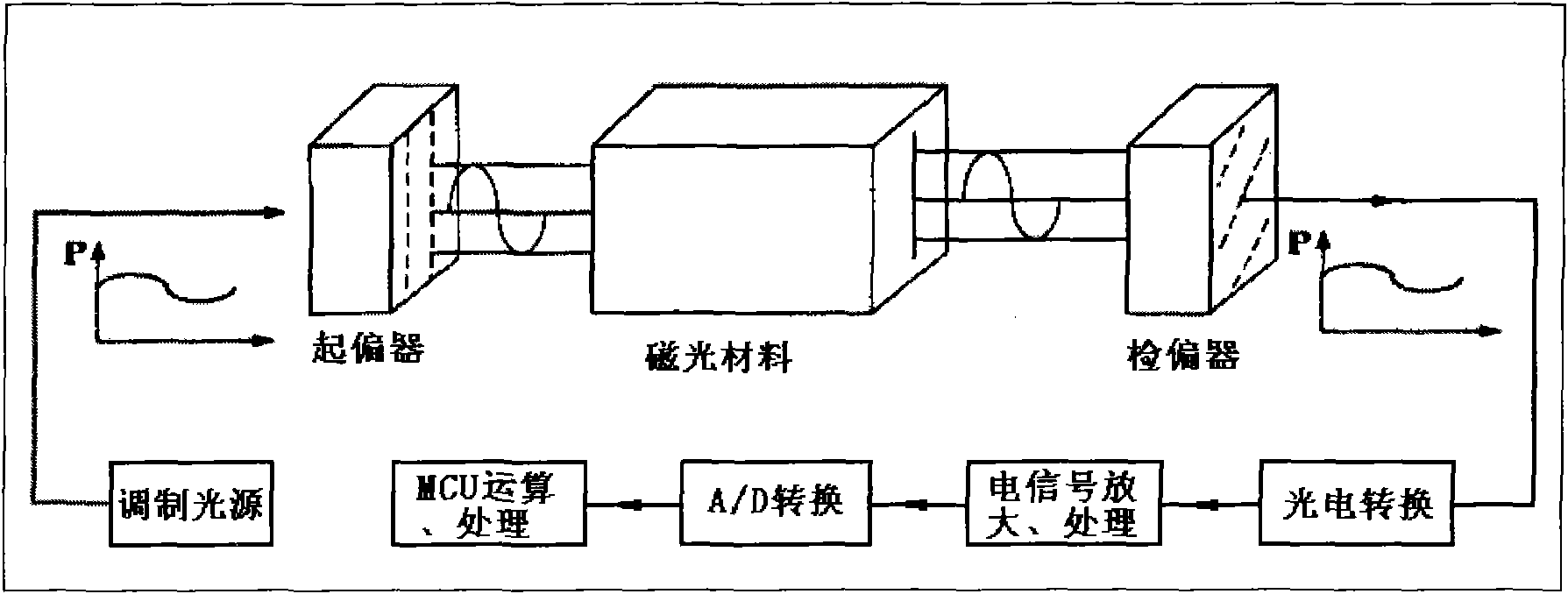
[0024] figure 2 It is the basic principle diagram of the optical current transformer based on the Faraday magneto-optical effect in the prior art. image 3 It is a schematic diagram of a primary current signal simulator of an optical current transformer based on the Faraday magneto-optical effect applying the concept of the present invention.

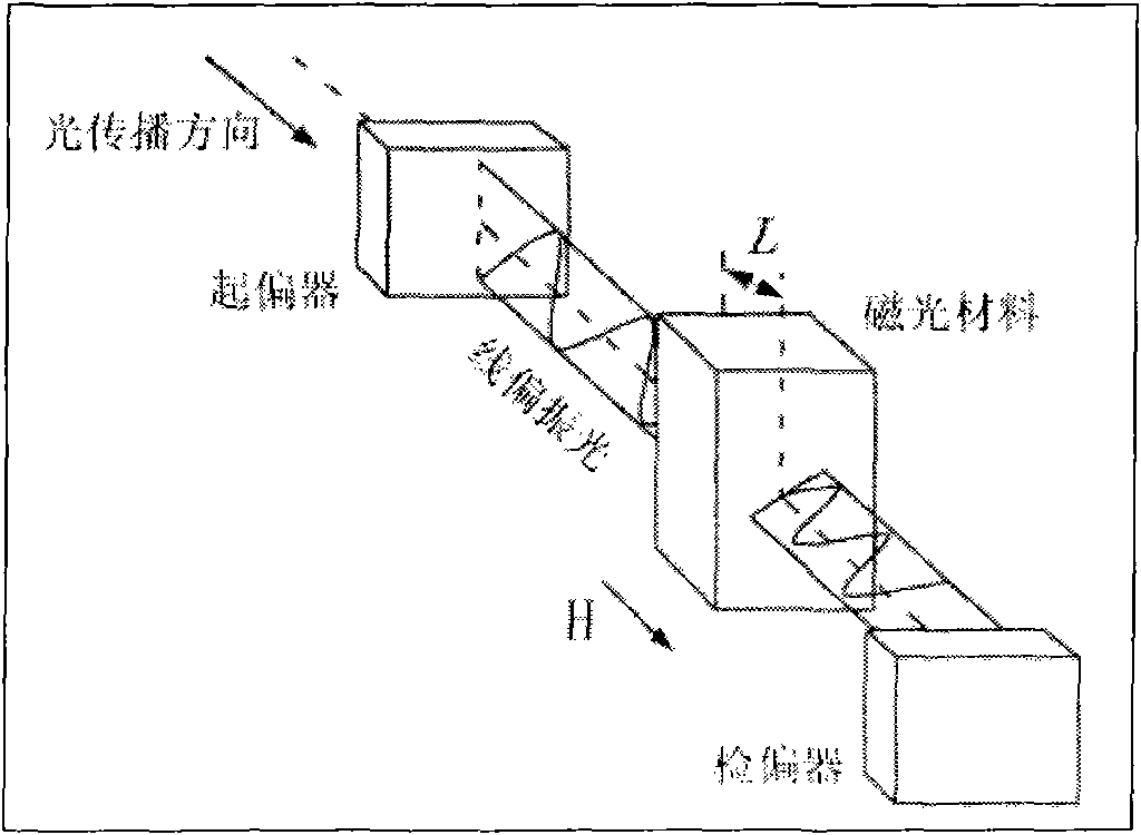
[0025] in the prior art figure 2 In the above, the light source generates light with constant power. After the light passes through the polarizer, it becomes linearly polarized light. After the linearly polarized light passes through the magneto-optical material placed in the magnetic field, the polarization angle is deflected. The deflection angle and the magnetic field in which it is located Proportional to the magnetic field strength, that is, proportional to the current to be measured. After the deflected polarized light...


PUM


Abstract

The invention provides a primary current signal simulator for an optical current transformer based on a faraday effect. The optical current transformer comprises a light source, a polarizer, a deflector of magneto-optical material, a polarization analyzer, a photoelectric conversion module, an electrical signal amplification and processing module, an analog / digital conversion module and a micro control unit (MCU) operation and processing module, wherein the light source is a modulated light source capable of replacing a constant power light source in the optical current transformer based on the faraday effect, so as to ensure that the changes of optical power output by the polarization analyzer when the deflector of the magneto-optical material is not positioned in a magnetic field are the same as the changes of optical power output when the deflector of the magneto-optical material is positioned in the magnetic field.

Description

technical field [0001] The invention relates to a smart grid, in particular to an optical current transformer based on the Faraday magneto-optic effect used in the smart grid and a primary current signal simulator used for the optical current transformer. Background technique [0002] In recent years, resource and environmental issues have become the focus of common attention of all countries in the world. Under this situation, smart grid has gradually become a new trend and new trend in the development of modern power grids. In the smart grid, current transformers and voltage transformers are responsible for converting the current and voltage states of the grid into signals that can be processed by other power intelligent equipment. They are the basis for measurement and protection and other intelligent devices. In the research and development of the sensor, the optical current transformer based on the Faraday magneto-optical effect is one of the important directions. [0...

Claims


Application Information

Patent Timeline
Patent Type & Authority Applications(China)
IPC IPC(8): G01D5/30H05B37/02
Inventor 朱宏兵
Owner BEIJING DERUN CENTURY TECH
Learn More