Device and method for measuring solid circulation flow rate

A circulating flow rate and measuring device technology, which is applied in the direction of mass flow measuring device, etc., can solve problems such as difficult to meet the measurement requirements of high solid circulating flow rate and high solid circulating flow rate, and achieve the effect of simple structure, large land occupation and increased cost

Active Publication Date: 2012-10-31
INST OF ENGINEERING THERMOPHYSICS - CHINESE ACAD OF SCI
View PDF5 Cites 6 Cited by
  • Summary
  • Abstract
  • Description
  • Claims
  • Application Information

AI Technical Summary

Problems solved by technology

[0011] In summary, no matter it is the direct observation method, the butterfly valve method, or the companion bed method, it is d

Method used


Image

  • Device and method for measuring solid circulation flow rate
  • Device and method for measuring solid circulation flow rate
  • Device and method for measuring solid circulation flow rate

Examples


Embodiment 1

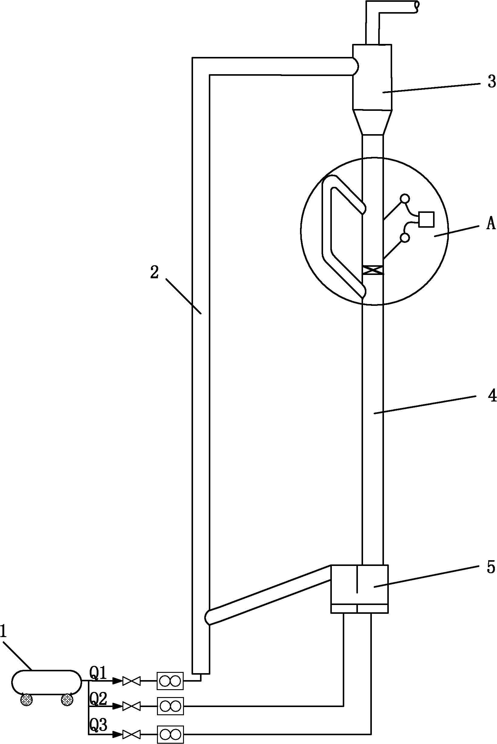
[0046] figure 1 It is a structural schematic diagram of a solid circulating flow rate measuring device of the present invention. A circulating fluidized bed is mainly composed of an air compressor 1, a riser 2, a cyclone separator 3, a material leg 4 and a feeder 5. Air compressor 1 is used as an air source, mainly providing three parts of air: Q1, Q2 and Q3. Q1 is used as the fluidizing medium of the riser 2, and Q2 and Q3 are used as the fluidizing gas and loosening gas of the feeder 5 respectively. Q1 fluidizes the solid particles in the riser and carries the solid particles through the cyclone separator 3. Through the gas-solid separation of the cyclone separator 3, the solid particles are discharged from the lower ash hopper into the dipleg 4, and the gas is discharged from the cyclone center tube. Q2 and Q3 make the solid particles enter the riser 2 from the dipleg 4 through the feeder 5 for circulation. The inner diameter of the riser 2 is Dr, and the accumulation an...

Embodiment 2

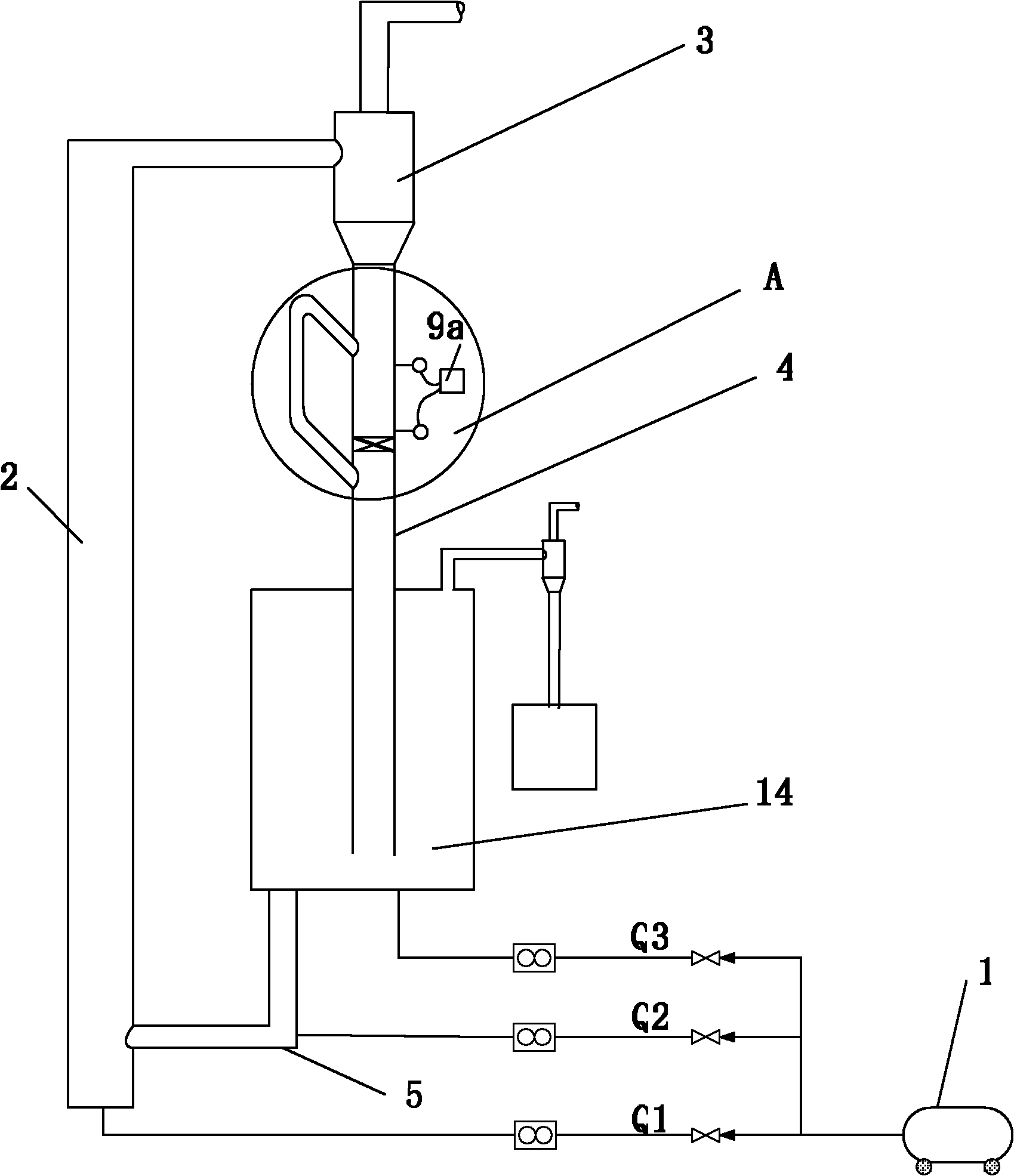
[0059] figure 2 It is another structural schematic diagram of a solid circulating flow rate measuring device of the present invention. A circulating fluidized bed is mainly composed of an air compressor 1, a riser 2, a cyclone separator 3, a material leg 4, a feeder 5 and a bubbling bed or a turbulent bed 14. The air compressor 1 is used as an air source, and mainly provides three parts of air, namely Q1, Q2 and Q3. Q1 serves as the fluidizing medium of the riser 2, and Q2 and Q3 serve as the return air of the feeder 5 and the fluidization air of the bubbling bed or turbulent bed 14, respectively. Q1 fluidizes the solid particles in the riser and carries the solid particles through the cyclone separator 3, through the gas-solid separation of the cyclone separator 3, the solid particles enter the bubbling bed or turbulent bed 14 from the lower end material leg 4 of the cyclone separator 3, Gas is discharged from the cyclone center cylinder. Q2 and Q3 make the solid particle...


PUM


Abstract

The invention discloses a device and a method for measuring solid circulation flow rate, which relate to the solid transmission technology. The device for measuring solid circulation flow rate is composed of components, such as a valve, a high-low stock level switch, a timing device, a material measuring section, a balance pipe and the like. The position of the material is detected through the high-low stock level switch, a signal is transmitted to the timing device, and the material accumulation time is displayed, so that manual timing error is avoided, and measurement accuracy is improved greatly. The material measuring section of the device provided by the invention can be obtained by directly selecting one section of a dip leg, and the device is simple in structure and convenient to operate. With the balance pipe, the interference of the measuring process on the system operation can be reduced, and the device for measuring solid circulation flow rate is especially suitable for measuring the solid circulation flow rate of the devices with high solid circulation flow rate, and also can be used for measuring the solid circulation flow rate under a pressurization condition.

Description

technical field [0001] The invention relates to the technical field of solid transmission in energy, chemical industry and related fields. It is a device and method for measuring the circulating flow rate of solids under normal pressure and pressurized conditions, which is suitable for measuring circulating fluidized bed boilers and circulating fluidized bed gasifiers. It is more suitable for measuring the solid circulation flow rate of devices with high solid circulation flow rate such as dense phase transport bed gasifier, fluid catalytic cracking (FCC), n-butane oxidation, etc. . technical background [0002] In the field of circulating fluidized bed, the solid circulating flow rate is a very important technical index. At present, the conventional measurement methods of solid circulation flow rate include: direct observation method, butterfly valve measurement method, companion bed method, etc. [0003] Direct observation method: Install a scale on the wall of the trans...

Claims


Application Information

Patent Timeline
IPC IPC(8): G01F1/76
Inventor 肖云汉阳绍军崔超宇廖良良王圣典赵凯李喜全徐祥
Owner INST OF ENGINEERING THERMOPHYSICS - CHINESE ACAD OF SCI
Why Eureka
Try Eureka