Method for inverting anisotropy parameters using variable offset vertical seismic profile data

A technology of vertical seismic profile and variable offset, applied in the field of seismic exploration data processing, can solve the problems of large error of linear inversion method, inability to accurately represent anisotropic model parameters, and inability to effectively restore nonlinear relationship, etc.

Active Publication Date: 2012-10-31
BC P INC CHINA NAT PETROLEUM CORP +1
View PDF2 Cites 25 Cited by
  • Summary
  • Abstract
  • Description
  • Claims
  • Application Information

AI Technical Summary

Problems solved by technology

However, the subsurface medium cannot be accurately represented by the two-dimensional flat VTI medium or the equivalent two-dimensional undulating TTI medium; the linear approximation cannot accurately represent the relationship between the anisotropic model parameters and the first arrival travel time and polarization data. Linear inversion based on approximation cannot effectively restore the nonlinear relationship between anisotropic model parameters and first arrival travel time and polarization data; methods based on weak anisotropy assumptions are not universal; linear inversion methods have large errors , the search ability of the enumeration method is limited

Method used


Image

  • Method for inverting anisotropy parameters using variable offset vertical seismic profile data
  • Method for inverting anisotropy parameters using variable offset vertical seismic profile data
  • Method for inverting anisotropy parameters using variable offset vertical seismic profile data

Examples


example 1

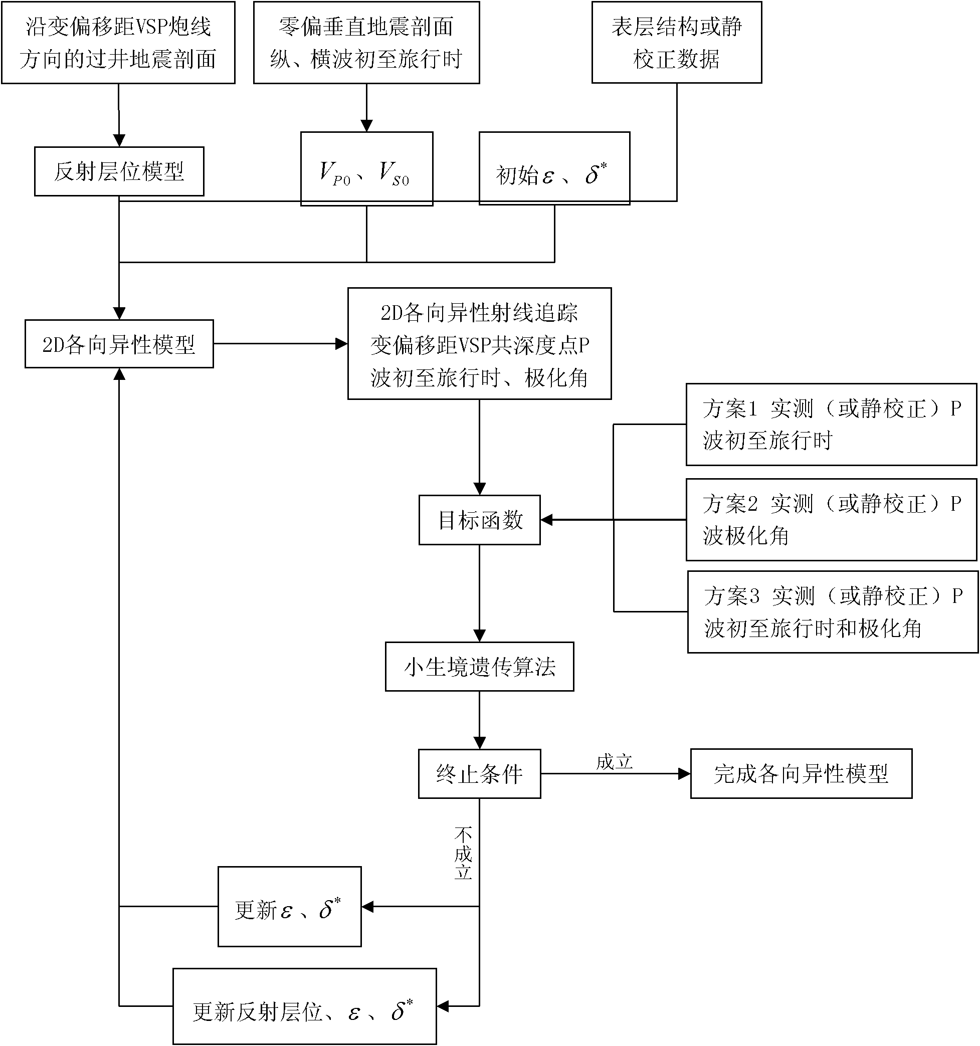
[0301] Example 1 theoretical model Figure 5 , the size is 4000m×2000m, the well is located at X=2000m, the initial shot point X=80m, the shot point spacing is 80m, 49 shots are collected, and the receiver points are located at Z=800m, 1200m, 1600m, first arrival travel time and polarization angle see Image 6 . The model includes 4 reflective surfaces, 1 horizontal, 1 monocline, and 2 undulating. During the inversion, it is assumed that the vertical compressional wave velocity and the reflection interface are known, and the calculation is performed sequentially from the shallow layer to the deep layer, and the anisotropy parameters ε, δ of each layer of the 2nd, 3rd, and 4th layers are calculated * .

[0302] (1) The objective function is established by using the first arrival travel time, the relative errors of the anisotropic parameter inversion of the second layer are -0.0003, -0.0031, and the standard deviation of travel time std=0.006ms; the relative error of the aniso...

example 2

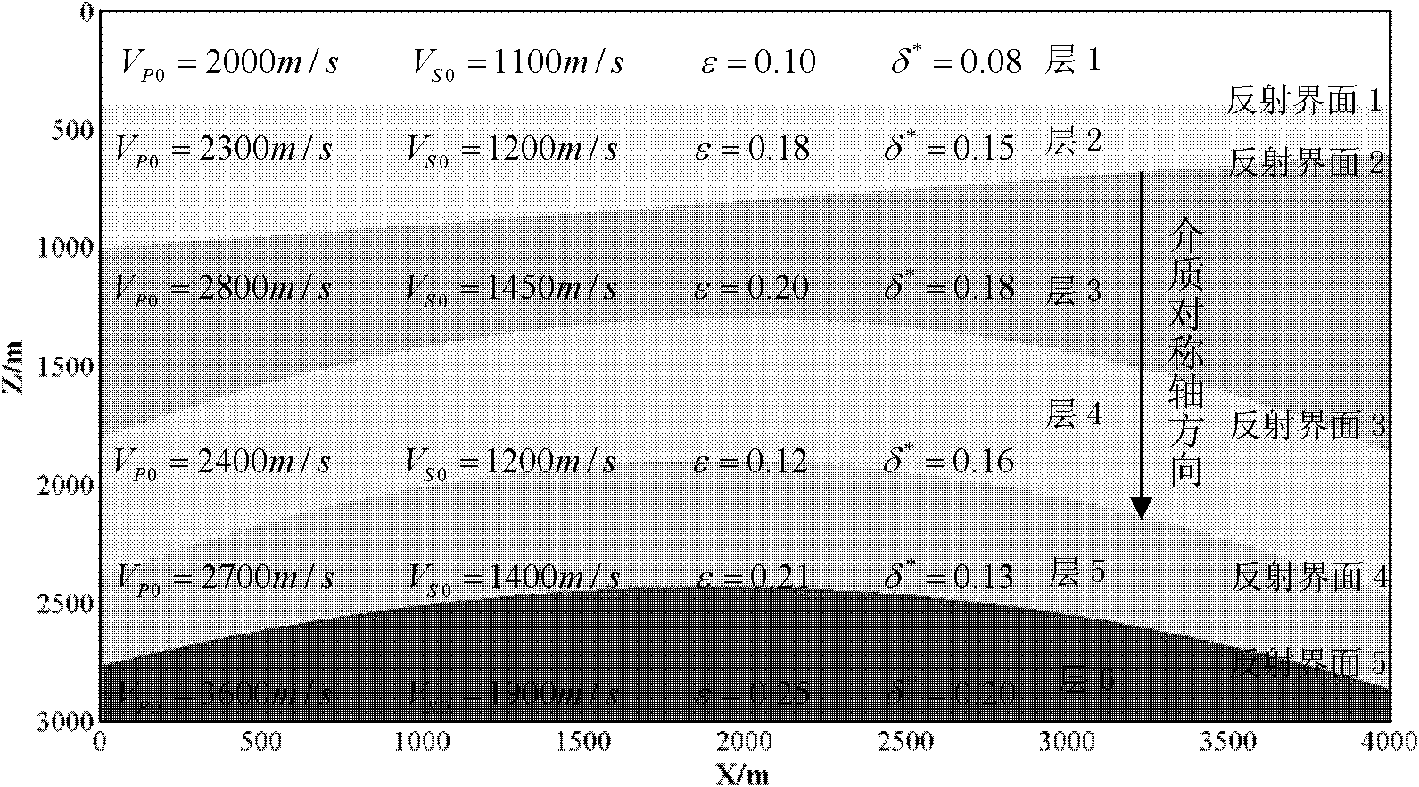
[0305] Example 2 Theoretical Model Figure 11 , the model size is 4000m×3000m, the well is located at X=2000m, the initial shot point X=80m, the shot point spacing is 80m, 49 shots are collected, the receiver points are located at Z=700m, 1200m, 1900m, 2400m, the first arrival travel time and polarization Kakumi Figure 12 . The model includes 5 reflective surfaces, 1 horizontal, 1 monocline, and 3 undulating. During the inversion, it is assumed that the vertical P-S wave velocity is known, and the calculations are performed sequentially from the shallow layer to the deep layer to obtain the anisotropy parameters of layers 2, 3, 4, and 5 and the shape parameters of reflection interfaces 1, 2, 3, and 4. The objective function is established by combining the first arrival travel time and polarization angle, the error analysis of the inversion results is shown in Table 1, and the comparison between the inversion value and the true value is shown in Figure 13 .

[0306] Table...

example 3

[0308] Example 3 Field measured WVSP data, 43 shot acquisitions, shot spacing 180m, 16 level acquisitions, level spacing 10m, a total of 160 depth points were observed. At the same time, zero-biased P-wave and zero-biased shear waves were collected in this well; according to the first arrival of zero-biased Figure 14 , is divided into 22 layers, the velocity-depth model is established, and the P-S wave casing velocity and the P-S-wave velocity ratio of each layer are obtained at the same time, see Figure 15 . Each shot point is converted to model coordinates with the wellhead as a reference point, and each layer and receiving point is mapped from the actual coordinates to the model coordinates with the wellhead as a reference point.

[0309] According to the collected data, the WVSP observation range is that the formation can basically be represented by oblique layers. Establish the initial velocity-depth model of the flat layer, and select 12 depth points for anisotropy p...


PUM


Abstract

The invention relates to a method for inverting anisotropy parameters using variable offset vertical seismic profile data. The method includes: calculating vertical longitudinal wave speed and vertical transverse wave speed of each layer of a vertical seismic profile; collecting symbol layer positions and determining intersections of each layer and well trajectory; building up a surface layer model and an observing system; randomly initiating the anisotropy parameters of layers to be determined and cubic coefficient of a top layer interface to be determined; forming anisotropy speed models to be optimized; screening receiver inter-layer points ; collecting shot first arrival to calculate polarizing angles; building up a target function using P wave first arrival travel time and the polarizing angles; using niche genetic algorithm to optimize the target function; finishing optimization of the anisotropy parameters of the layers to be determined and configuration of the top layer interface to be determined; calculating layer by layer 'from shallow deprocessing to deep deprocessing' to finish optimization of the anisotropy parameters of the whole model. By the method, a reflecting interface is close to actual stratum, linear convergence ray tracing is high in calculation efficiency, complicated internal relations of anisotropy media are simplified, iterative test ray tracing modeling is guided by guide search of the niche genetic algorithm, and the anisotropy parameters and interface configurations are inverted and optimized nonlinearly.

Description

technical field [0001] The invention relates to seismic exploration data processing technology, and is a method for inverting anisotropic parameters of variable offset vertical seismic profile (Walkaway VSP) data. Background technique [0002] Walkaway VSP adopts the observation method of receiving in the well, and the seismic point moves along a well line on the ground. It is mainly used for structural imaging near the well and reservoir research. 3D VSP (3-dimensional vertical seismic profile) can be regarded as the composition of Walkaway VSP in different azimuths. The Walkaway VSP data contain rich velocity information and morphological parameters of the reflection interface, which are expressed as changes in arrival travel time and polarization angle. [0003] Thomsen (1986) proposed anisotropy parameters with clear physical meaning, and gave the phase velocity and group velocity expressions of arbitrary strength and weak anisotropy, which brought the research of aniso...

Claims


Application Information

Patent Timeline
Patent Type & Authority Applications(China)
IPC IPC(8): G01V1/28G06N3/12
Inventor 李建国李彦鹏容娇君
Owner BC P INC CHINA NAT PETROLEUM CORP
Why Eureka
Try Eureka