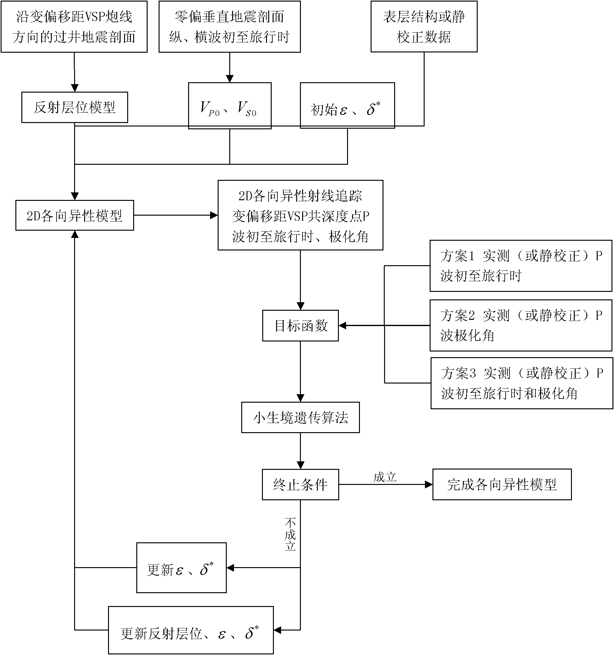
Method for inverting anisotropy parameters using variable offset vertical seismic profile data
A vertical seismic profile and variable offset technology, applied in the field of seismic exploration data processing, can solve problems such as inability to effectively restore nonlinear relationships, limited search capabilities of enumeration methods, and large errors in linear inversion methods
- Summary
- Abstract
- Description
- Claims
- Application Information
AI Technical Summary
Problems solved by technology
Method used
Image
Examples
example 1
[0301] Example 1 theoretical model Figure 5 , the size is 4000m×2000m, the well is located at X=2000m, the initial shot point X=80m, the shot point spacing is 80m, 49 shots are collected, and the receiver points are located at Z=800m, 1200m, 1600m, first arrival travel time and polarization angle see Figure 6 . The model includes 4 reflective surfaces, 1 horizontal, 1 monocline, and 2 undulating. During the inversion, it is assumed that the vertical compressional wave velocity and the reflection interface are known, and the calculation is performed sequentially from the shallow layer to the deep layer, and the anisotropy parameters ε, δ of each layer of the 2nd, 3rd, and 4th layers are calculated * .
[0302] (1) The objective function is established by using the first arrival travel time, the relative errors of the anisotropic parameter inversion of the second layer are -0.0003, -0.0031, and the standard deviation of travel time std=0.006ms; the relative error of the anis...
example 2
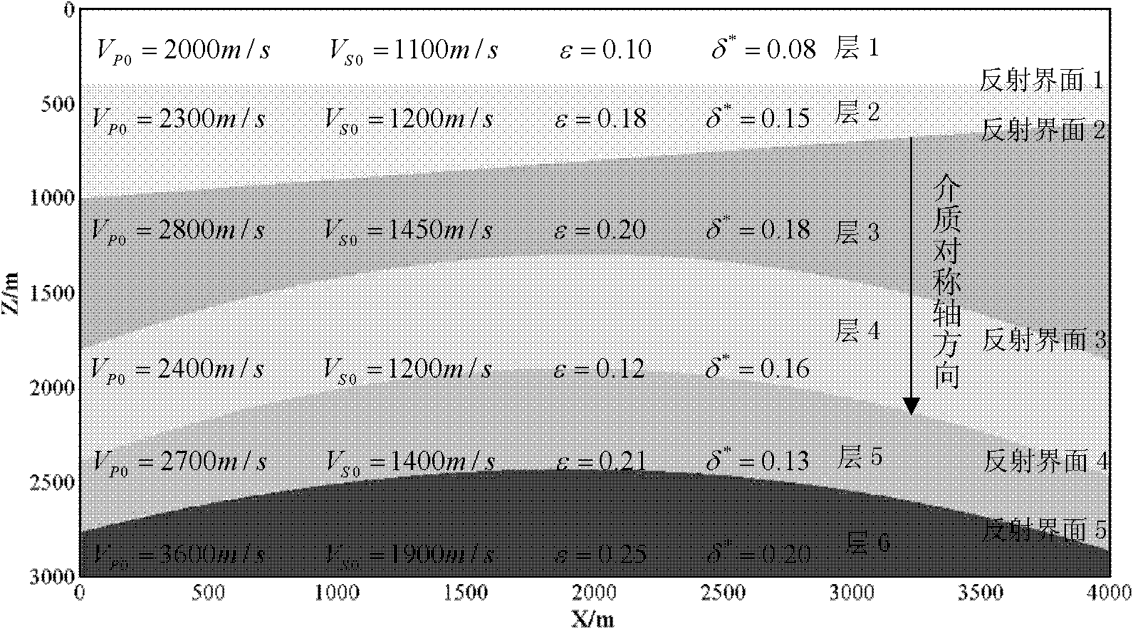
[0305] Example 2 Theoretical Model Figure 11 , the model size is 4000m×3000m, the well is located at X=2000m, the initial shot point X=80m, the shot point spacing is 80m, 49 shots are collected, the receiver points are located at Z=700m, 1200m, 1900m, 2400m, the first arrival travel time and polarization Kakumi Figure 12 . The model includes 5 reflective surfaces, 1 horizontal, 1 monocline, and 3 undulating. During the inversion, it is assumed that the vertical P-S wave velocity is known, and the calculations are performed sequentially from the shallow layer to the deep layer to obtain the anisotropy parameters of layers 2, 3, 4, and 5 and the shape parameters of reflection interfaces 1, 2, 3, and 4. The objective function is established by combining the first arrival travel time and polarization angle, the error analysis of the inversion results is shown in Table 1, and the comparison between the inversion value and the true value is shown in Figure 13 .
[0306] Table...
example 3
[0308] Example 3 Field measured WVSP data, 43 shot acquisitions, shot spacing 180m, 16 level acquisitions, level spacing 10m, a total of 160 depth points were observed. At the same time, zero-biased P-wave and zero-biased shear waves were collected in this well; according to the first arrival of zero-biased Figure 14 , is divided into 22 layers, the velocity-depth model is established, and the P-S wave casing velocity and the P-S-wave velocity ratio of each layer are obtained at the same time, see Figure 15 . Each shot point is converted to model coordinates with the wellhead as a reference point, and each layer and receiving point is mapped from the actual coordinates to the model coordinates with the wellhead as a reference point.
[0309] According to the collected data, the WVSP observation range is that the formation can basically be represented by oblique layers. Establish the initial velocity-depth model of the flat layer, and select 12 depth points for anisotropy p...
PUM
 Abstract
Description
Claims
Application Information
 - R&D
- Intellectual Property
- Life Sciences
- Materials
- Tech Scout
- Unparalleled Data Quality
- Higher Quality Content
- 60% Fewer Hallucinations
Browse by: Latest US Patents, China's latest patents, Technical Efficacy Thesaurus, Application Domain, Technology Topic, Popular Technical Reports.
© 2025 PatSnap. All rights reserved.Legal|Privacy policy|Modern Slavery Act Transparency Statement|Sitemap|About US| Contact US: help@patsnap.com


