Phase plate for wavefront coding imaging and bandwidth-adjustable wavefront coding system

A technology of wavefront encoding and encoding system, applied in the field of phase plate and bandwidth adjustable wavefront encoding system, phase plate and wavefront encoding system, which can solve the problem of limited image detector, reduced imaging quality, and lack of adjustable imaging system Bandwidth and other issues to achieve the effect of weakening the spectrum aliasing effect, reducing interference, and suppressing defocus

Active Publication Date: 2012-10-31
XI'AN INST OF OPTICS & FINE MECHANICS - CHINESE ACAD OF SCI
View PDF7 Cites 16 Cited by
  • Summary
  • Abstract
  • Description
  • Claims
  • Application Information

AI Technical Summary

Problems solved by technology

However, none of the existing non-rotationally symmetric phase plates has the ability to adjust the bandwidth of the imaging system
Most current digital imaging syste

Method used


Image

  • Phase plate for wavefront coding imaging and bandwidth-adjustable wavefront coding system
  • Phase plate for wavefront coding imaging and bandwidth-adjustable wavefront coding system
  • Phase plate for wavefront coding imaging and bandwidth-adjustable wavefront coding system

Examples


Embodiment Construction

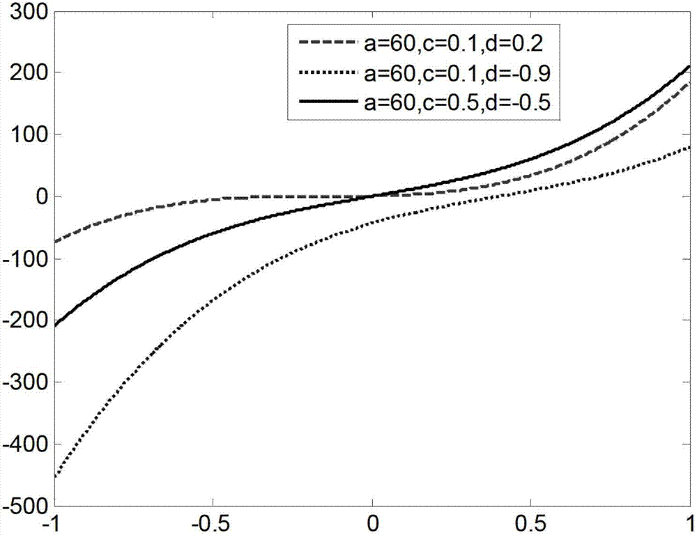
[0031] The invention provides a phase plate for wavefront encoding imaging. The phase distribution function of the phase plate for wavefront encoding imaging is formed by superposition of two third-order power functions with relative displacements. The one-dimensional function expression for:

[0032] f=α·(x+c) 3 +α·(x+d) 3

[0033] in:

[0034] α, c, d are the parameters of the above phase distribution function, where α represents the phase modulation intensity of the phase plate (?20π, and should be obtained through optimization according to the specific situation), and c and d represent the relative The displacement of the center of the aperture plane; since x is the normalized coordinate, and c and d are the translation relative to the normalized coordinate system, the value ranges of x, c, and d are all [-1, 1] .

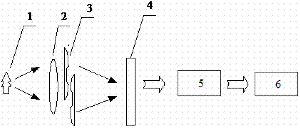
[0035] At the same time, the present invention also provides a bandwidth-tunable wavefront encoding system based on the above-mentioned phase plate for wa...


PUM


Abstract

The invention relates to a phase plate for wavefront coding imaging and a bandwidth-adjustable wavefront coding system. A phase distribution function of the phase plate is formed by the overlapping two 3-order power functions with relative displacement, wherein a one-dimensional function expression is: f=alpha.(x+c)<3>+alpha.(x+d)<3>. The invention provides the phase plate for the wavefront coding imaging and the bandwidth-adjustable wavefront coding system which can effectively expand the system depth of field, can change the effects of a system imaging bandwidth, can effectively reduce the influences of frequency spectrum mixing and overlapping on the imaging quality, as well as can further develop the potential application capability of a wavefront coding imaging technology.

Description

technical field [0001] The invention belongs to the field of optics, and relates to a phase plate and a wavefront coding system, in particular to a phase plate and a bandwidth-adjustable wavefront coding system for wavefront coding imaging. Background technique [0002] The depth of field of extended optical systems has always been a hotspot in academic research. Since the mid-1980s, although various methods have been proposed for depth of field expansion, it was not until Dr. Dowski and Professor Cathey of the University of Colorado in the United States proposed the wavefront in 1995. After the concept of coding, the extension of depth of field had a real breakthrough. [0003] Taking the one-dimensional optical system as an example, its defocus optical transfer function OTF can be obtained through the autocorrelation operation of the generalized pupil function, as follows: [0004] H ( u , ...

Claims


Application Information

Patent Timeline
IPC IPC(8): G02B5/30G02B27/00
Inventor 赵惠易红伟李英才
Owner XI'AN INST OF OPTICS & FINE MECHANICS - CHINESE ACAD OF SCI
Why Eureka
Try Eureka