Switched-mode power supply

A technology of switching power supply and switching element, which is applied in the direction of output power conversion device, electrical components, and electric variable adjustment, can solve the problems of increased cost, increased number of components, increased number of external terminals, etc., and achieves the effect of reducing the occupied area

Inactive Publication Date: 2012-10-31
MITSUMI ELECTRIC CO LTD
View PDF1 Cites 41 Cited by
  • Summary
  • Abstract
  • Description
  • Claims
  • Application Information

AI Technical Summary

Problems solved by technology

[0009] Therefore, a terminal for connecting the capacitor Cff is required in addition to the terminal for applying the output voltage, so the number of external terminals (the number of pins) increases, leading to an increase in cost.
In addition, due to the limitation of the number of external terminals of the IC, it may not be possible to mount the ripple injection function.
In addition, since the feedforward capacitor Cff in the switching power supply of Patent Document 1 is an element with a large capacitance value, there is a problem that an external element needs to be used, and the number of parts increases.

Method used


Image

  • Switched-mode power supply
  • Switched-mode power supply
  • Switched-mode power supply

Examples


Embodiment Construction

[0031] Hereinafter, preferred embodiments of the present invention will be described based on the drawings.

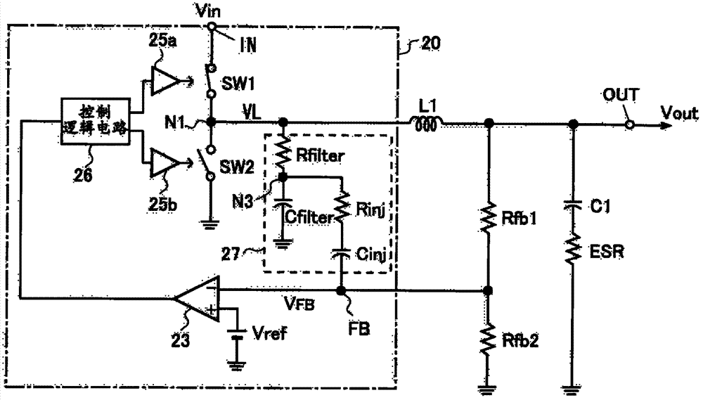
[0032] figure 1 An embodiment of a switching regulator type DC-DC converter to which the present invention is applied is shown.

[0033] The DC-DC converter of this embodiment includes a coil L1 serving as an inductor, and a high-side driver that flows a drive current into the coil L1 and is connected between a voltage input terminal IN to which a DC input voltage Vin is applied and one terminal of the coil L. The switch element SW1 and the low-side rectification switch element SW2 connected between one terminal of the coil L1 and the ground point are used. The switching element SW1 for driving and the switching element SW2 for rectification can be comprised by MOSFET (Insulated Gate Field Effect Transistor), for example.

[0034]In addition, the DC-DC converter of the present embodiment includes a switch control circuit 20 for turning on and off the switching eleme...


PUM


Abstract

The present invention provides a switched-mode power supply. The ripple-control switched-mode power supply integrates a ripple injection function into an feedback voltage in a control circuit without increasing the number of external terminals. The ripple-control switched-mode power supply includes a control circuit 20 to switch on / off a drive switching element SW1 for making current through an inductor. The control circuit comprises: a voltage comparator 23 comparing the feedback voltage with a predetermined voltage; a ripple injection circuit 27, wherein the ripple injection circuit has an integrator outputting an integral of the voltage at the node between the driver switching element and the inductor, and a series RC circuit for adding a ripple component to the feedback voltage; and a control pulse generator 24 generating the control pulse based on an output of the voltage comparator. The switched-mode power supply is configured to switch on / off the drive switching element based on the control ripple generated by the control pulse generator.

Description

technical field [0001] The present invention relates to a switching regulator type DC-DC converter for converting DC voltage, and more particularly to a switching power supply device having a pulse injection function. Background technique [0002] As a circuit that converts a DC input voltage and outputs a DC voltage having a different potential, there is a DC-DC converter (DC-DC converter) of a switching regulator type. This DC-DC converter includes a driving switching element that applies a DC voltage supplied from a DC power source such as a battery to an inductor (coil) to cause a current to flow through the inductor (inductor), a rectifying element, and a control circuit. , causing the coil to store energy, the rectifying element rectifies the current of the coil during the energy release period when the driving switching element is turned off, and the control circuit controls the turning on and off of the driving switching element. [0003] Conventionally, as the cont...

Claims


Application Information

Patent Timeline
Patent Type & Authority Applications(China)
IPC IPC(8): H02M3/156H02M3/157H02M1/08
CPCH02M2001/0025H02M3/156H02M1/0025
Inventor 樋口义隆中岛平裕山中佑司
Owner MITSUMI ELECTRIC CO LTD
Why Eureka
Try Eureka