State switching method, inactive timer starting method and user equipment

A technology for user equipment and state switching, applied in the fields of state switching and two types of user equipment, can solve problems such as affecting scheduling timeliness and increasing data transmission delay, so as to reduce power consumption, save energy, and reduce data transmission delay Effect

Active Publication Date: 2012-10-31
HONOR DEVICE CO LTD
View PDF3 Cites 32 Cited by
  • Summary
  • Abstract
  • Description
  • Claims
  • Application Information

AI Technical Summary

Problems solved by technology

[0005] 1) After the UE receives the newly transmitted data UL Grant, immediately starting the Inactivity Timer to make the UE in the active state will cause more power consumption problems;
[0006] 2) If the Inactivity Timer starts early, the timeout will also be early, which will cause the UE to enter the inactive state prematurely, affect the timeliness of scheduling, and increase the delay of data transmission

Method used


Image

  • State switching method, inactive timer starting method and user equipment
  • State switching method, inactive timer starting method and user equipment
  • State switching method, inactive timer starting method and user equipment

Examples


Embodiment 1

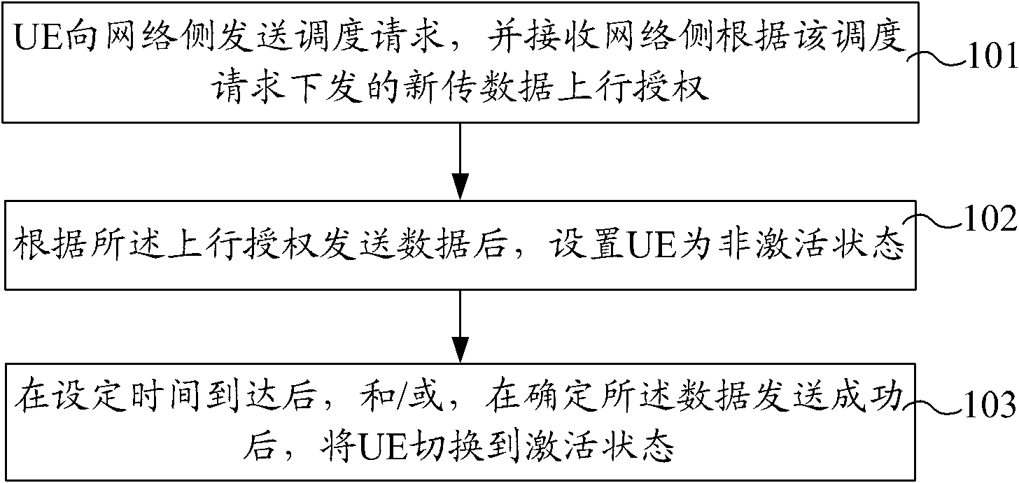
[0049] The UE power saving method provided in this embodiment, such as figure 1 shown, including the following steps:

[0050] Step 101, the UE sends a scheduling request (SR) to the network side, and receives a newly transmitted data uplink grant (UL Grant) issued by the network side according to the scheduling request;

[0051] Step 102, after sending data according to the UL Grant, set the UE to be in an inactive state;

[0052] Step 103: After the set time arrives, and / or after it is determined that the data is sent successfully, switch the UE to the active state.

[0053] The time set above can be realized by setting the first timer. For the convenience of description, the first timer will be called the IT prohibition timer later; when the UE is set to the inactive state, the IT prohibition timer is further started; the setting When the specified time arrives, the IT prohibits the timer from overtime.

[0054] After the above IT prohibition timer is started and before ...

Embodiment 2

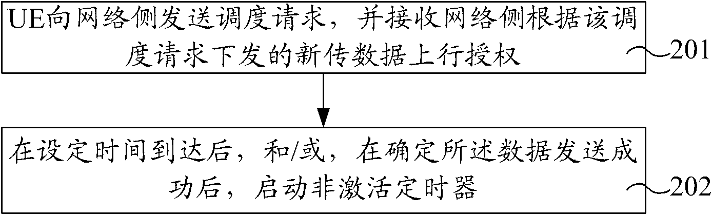
[0058] The method for reducing UE data transmission delay provided by this embodiment, such as figure 2 shown, including the following steps:

[0059] Step 201, the UE sends an SR to the network side, receives the newly transmitted data UL Grant issued by the network side according to the scheduling request, and sends data according to the UL Grant;

[0060] Step 202: Start an Inactivity Timer after the set time arrives, and / or after it is determined that the data is sent successfully.

[0061] In this embodiment, after the data is sent according to the UL Grant, the Inactivity Timer is not started immediately, but the Inactivity Timer is started only after the set time arrives, and / or after it is determined that the uplink data is sent successfully.

[0062] The above-mentioned set time can be realized by setting the first timer. For the convenience of description, the first timer is subsequently called the IT prohibition timer; then after sending data, the IT prohibition t...

Embodiment 3

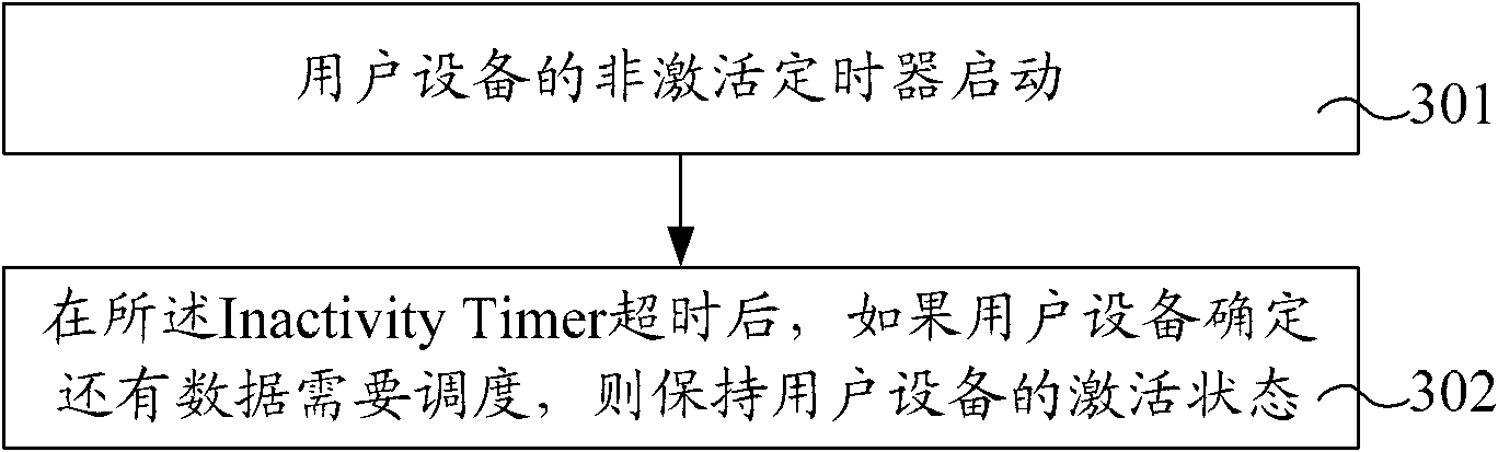
[0067] The method for reducing UE data transmission delay provided by this embodiment, such as image 3 shown, including the following steps:

[0068] Step 301, the Inactivity Timer of the UE is started;

[0069] The start of the Inactivity Timer in this step may be the start of the Inactivity Timer when the UE receives the UL Grant in the prior art, or it may be the one mentioned in any of the following embodiments 4 to 13 of the present invention The Inactivity Timer starts.

[0070] Step 302. After the Inactivity Timer expires, if the UE determines that there is still data to be scheduled, keep the active state of the UE.

[0071] In step 302, if the UE determines that no data needs to be scheduled, the UE executes DRX Cycle.

[0072] In step 302, if the UE determines that there is still data to be scheduled, the Inactivity Timer may also be restarted. After restarting the Inactivity Timer, it may return to step 302 to continue.

[0073] In addition, after the Inactivi...


PUM


Abstract

The invention provides a state switching method, an inactive timer starting method and user equipment (UE). The state switching method comprises the steps as follows: the UE sends a dispatching request to a network side and receives the newly-transmitted data ascending authorization sent by the network side according to the dispatching request; after the data is sent according to the ascending authorization, the UE is switched into an inactive state; after the setting time arrives and / or the data is sent successfully, the UE is switched into an active state. According to the invention, after the data is sent according to the newly-transmitted data ascending authorization, the UE is switched into an inactive state first; and after the setting time arrives and / or the data is sent successfully, the UE can be switched into the active state, thereby reducing the power consumption of the UE and saving the resources.

Description

technical field [0001] The invention relates to the field of wireless communication user equipment, in particular to a state switching method, a method for starting an inactive timer and two kinds of user equipment. Background technique [0002] In the existing Long Term Evolution (LTE) system, all user equipment (User Equipment, UE) that have established a connection with an evolved base station (evolved NodeB, eNB) share air interface resources, that is, the eNB transmits at each transmission time interval ( Transmission Time Interval (TTI) dynamically allocates transmission resources for subordinate UEs according to information such as the amount of UE data. In the uplink data scheduling, the UE reports its buffered data volume to the eNB by sending a buffer status report (Buffer Status Report, BSR), so as to provide reference information for the uplink scheduling of the eNB. [0003] Regardless of whether the UE is currently in an active state or an inactive state, when...

Claims


Application Information

Patent Timeline
Patent Type & Authority Applications(China)
IPC IPC(8): H04W52/02H04W52/28
CPCH04W72/1284H04W52/02H04W52/28H04W52/0216Y02B60/50H04W72/1289H04W52/0229H04W52/0251H04W76/28Y02D30/70
Inventor 权威唐珂韩广林张戬王瑜
Owner HONOR DEVICE CO LTD
Why Eureka
Try Eureka