Waste gas recovery processing system, and recovery processing technique of waste gas
A waste gas recovery and treatment system technology, which is applied to the separation of dispersed particles, chemical instruments and methods, separation methods, etc., can solve the problems of environmental pollution, incomplete treatment, and single scope of application, achieving remarkable results, energy saving and environmental protection. , to achieve the effect of recycling
- Summary
- Abstract
- Description
- Claims
- Application Information
AI Technical Summary
Problems solved by technology
Method used
Image
Examples
Embodiment 1
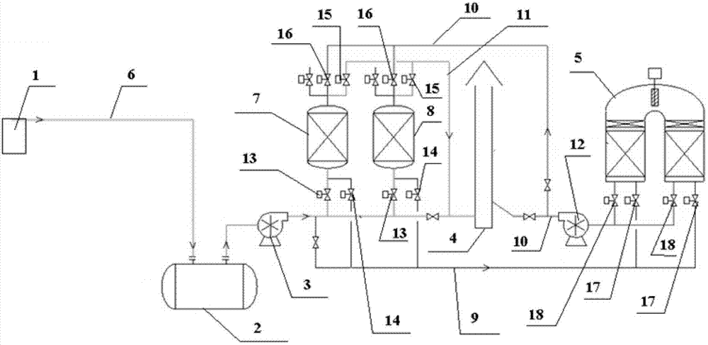
[0046] Such as figure 1 As shown, the exhaust gas recovery and treatment system of the present invention includes an exhaust gas conveying device 1, a buffering and stabilizing device 2, a booster device 3, a purified gas discharge device 4, and an adsorption device and a catalytic oxidation device 5 connected to each other. The exhaust gas conveying device 1 and the The above adsorption device is connected, the purified gas discharge device 4 is connected with the adsorption device and the catalytic oxidation device 5 respectively, and the exhaust gas conveying device 1, the buffering and stabilizing device 2, the booster device 3 and the adsorbing device are connected successively through the exhaust gas conveying pipeline 6 connection, where:
[0047] The adsorption device is a primary adsorption device, including a first adsorption tower 7 and a second adsorption tower 8 that can be used alternately;
[0048] The bottom of the first adsorption tower 7 and the second adsor...
Embodiment 2
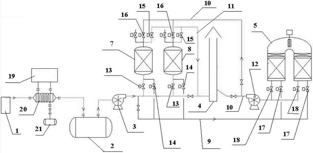
[0081] Such as figure 2 As shown, the setting and distribution of a waste gas recovery treatment system are the same as in Embodiment 1, the difference is:
[0082] It also includes a condensation recovery device, which includes a condenser 20 and a condensate recovery tank 21 connected to each other with a condensing unit 19; an exhaust gas conveying device 1, a condenser 20, a buffering and stabilizing device 2, and a booster device 3 and the adsorption device are sequentially connected through the waste gas delivery pipeline 6;
[0083] The waste gas conveying device 1 is a vault chemical storage tank located in a chemical storage irrigation area for discharging waste gas.
[0084] Apply the exhaust gas recovery treatment system of the present invention to an irrigation area comprising at least one organic chemical vault storage tank, and the process for waste gas recovery treatment is the same as in Example 1, except for the following steps:
[0085] In step (1), the exha...
Embodiment 3
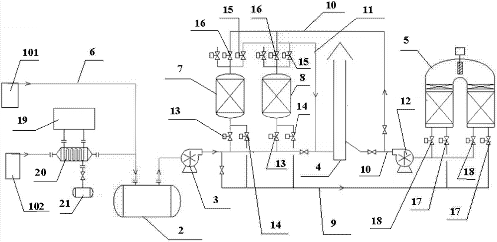
[0090] Such as image 3 As shown, the setting and distribution of a waste gas recovery treatment system are the same as in Embodiment 1 and Embodiment 2, the difference is:
[0091] The exhaust gas conveying device 1 is a chemical irrigation area of a chemical storage irrigation area including a floating roof chemical storage tank 101 and a vaulted chemical storage tank 102;
[0092] The floating roof chemical storage tank 101, the buffering and stabilizing device 2, the pressurizing device 3 and the adsorption device are sequentially connected through the waste gas conveying pipeline 6;
[0093] The condensation recovery device includes a condenser 20 and a condensate recovery tank 21 which are connected to each other and are provided with a condensing unit 19;
[0094] The vaulted chemical storage tank 102 , the condenser 20 , the buffering and stabilizing device 2 , the pressurizing device 3 and the adsorption device are sequentially connected through the waste gas conve...
PUM
| Property | Measurement | Unit |
|---|---|---|
| Specific surface | aaaaa | aaaaa |
| Specific surface | aaaaa | aaaaa |
| Specific surface | aaaaa | aaaaa |
Abstract
Description
Claims
Application Information
 - R&D
- Intellectual Property
- Life Sciences
- Materials
- Tech Scout
- Unparalleled Data Quality
- Higher Quality Content
- 60% Fewer Hallucinations
Browse by: Latest US Patents, China's latest patents, Technical Efficacy Thesaurus, Application Domain, Technology Topic, Popular Technical Reports.
© 2025 PatSnap. All rights reserved.Legal|Privacy policy|Modern Slavery Act Transparency Statement|Sitemap|About US| Contact US: help@patsnap.com


