Electron beam synchronous powder feeding and quick forming method

A technology of synchronous powder feeding and electron beam, applied in metal material coating process, melting spray plating, coating and other directions, can solve the problems of difficult to process large parts, difficult to process shape height, low material deposition speed, etc., to achieve forming The effect of high speed, increased size of forming, and fast melting and accumulation

Inactive Publication Date: 2012-11-07
BEIJING AERONAUTICAL MFG TECH RES INST
View PDF2 Cites 21 Cited by
  • Summary
  • Abstract
  • Description
  • Claims
  • Application Information

AI Technical Summary

Problems solved by technology

[0010] Restricted by the shape and processing technology of the wire itself, it is difficult for the rapid prototyping technology of electron beam fuse deposition to process structures with highly complex shapes.
[0011] 2. The electron beam selective melting technology based on powder spreading is almost not restricted by the shape of the part, and can process any complex parts, but it is difficult to process large parts due to the limitation of the powder spreading device and the deflection angle of the electron beam; it is different from wire filling or powder feeding In contrast, the material deposition rate is very low, and the processing of gradient materials is limited

Method used


Image

  • Electron beam synchronous powder feeding and quick forming method
  • Electron beam synchronous powder feeding and quick forming method
  • Electron beam synchronous powder feeding and quick forming method

Examples


Embodiment Construction

[0035] The technology of the present invention will be further described below in conjunction with accompanying drawing and embodiment:

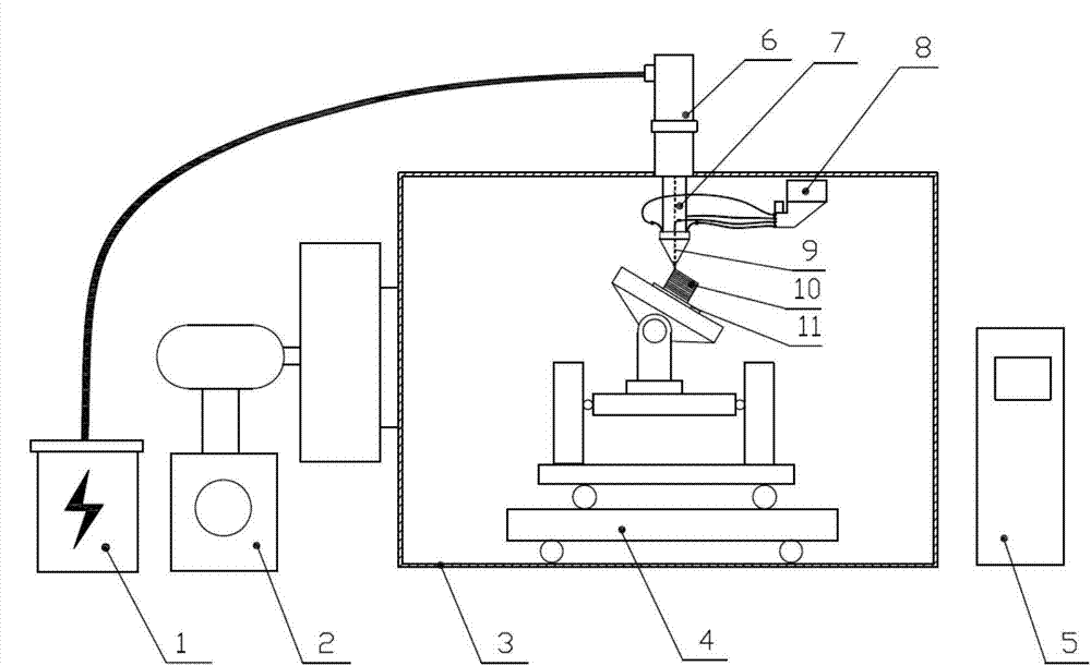
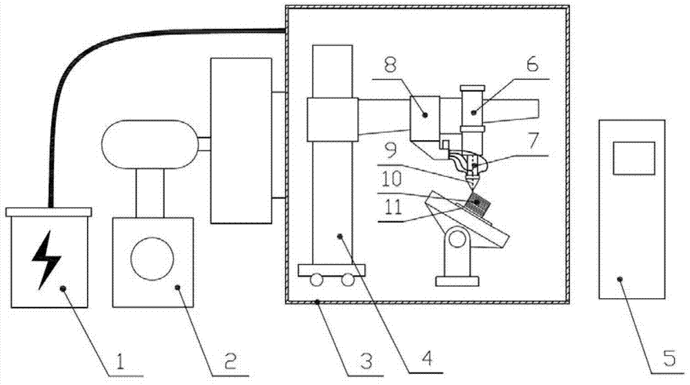
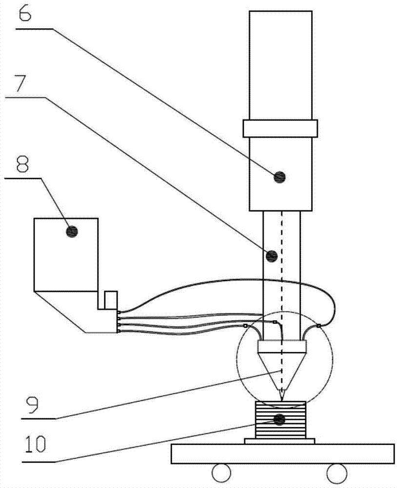
[0036] attached figure 1 Provided is a structural schematic diagram of a fixed-gun synchronous powder-feeding electron beam rapid prototyping equipment implementing the technical solution of the present invention. Powder nozzle 7 produces relative movement. The high-voltage power supply and cable 1 of the equipment are connected to the electron gun 6, the vacuum unit 2 communicates with the main vacuum chamber 3, the electron gun 6 is fixed on the outside of the top of the vacuum chamber 3, the coaxial powder feeding nozzle 7 is fixed on the lower part of the electron gun 6, and the powder feeder 8 passes through the tube The road is connected with the coaxial powder feeding nozzle 7, the multi-axis workbench 4 is placed inside the vacuum chamber 3, and the control cabinet 5 controls the whole equipment. The powder feeder 8 and the workpie...


PUM

PropertyMeasurementUnit
particle sizeaaaaaaaaaa

Abstract

The invention discloses an electron beam synchronous powder feeding and quick forming method. The method includes that metal powder is fed to a portion, which is intersected with beam current, of a to-be-processed surface, in a coaxial or paraxial manner, and the portion can be positioned in a molten pool or at the front of the molten pool. The electron beam synchronous powder feeding and quick forming method is characterized in that an electron beam bombards a workpiece to form the molten pool, the molten pool moves relative to the surface of the workpiece, the metal powder is simultaneously fed to a thermal action zone to participate in melting, and processing is implemented. As the powder is fed, the synchronous powder feeding and quick forming method has the advantages that speed is fast, quality is good, chemical composition and structure property of a part can be conveniently regulated and controlled, and the method is particularly applicable to preparing high-gradient and multi-step materials and structures and also can be used for processing parts with fine appearances and dimensions. Compared with wire feeding technology, the electron beam synchronous powder feeding and quick forming method has the powder does not interfere with the part, technological difficulty is low, and the method is easy to control.

Description

technical field [0001] The invention relates to a rapid prototyping method for electron beam synchronous powder feeding, which belongs to the technical field of rapid prototyping, manufacturing and repairing of metal parts. Background technique [0002] The invention relates to a synchronous powder-feeding electron beam rapid prototyping process and device, which is suitable for the rapid prototyping direct manufacture and repair of metal parts; the preparation of high-gradient or multi-gradient metal materials, the preparation of metal matrix composite materials, and the like. [0003] Electron beam rapid prototyping direct manufacturing technology of metal parts is a new metal solid additive processing technology developed in recent years. At present, from the technical form, it can be divided into electron beam fuse deposition technology based on melting and feeding wire and electron beam selective melting technology based on melting pre-coated powder. The common princip...

Claims


Application Information

Patent Timeline
Patent Type & Authority Applications(China)
IPC IPC(8): B22F3/115C23C4/00B33Y10/00B33Y30/00
Inventor 锁红波吴冰李晋炜陈哲源杨洋杨光李怀学巩水利
Owner BEIJING AERONAUTICAL MFG TECH RES INST
Why Eureka
Try Eureka