Eureka AIR delivers breakthrough ideas for toughest innovation challenges, trusted by R&D personnel around the world.

Electric lifting table with spring balanced design

A spring balance, lifting platform technology, applied in the direction of lifting frame, lifting device, etc., can solve the problems of wasting energy, reducing system efficiency, and the inability to realize the lifting platform of the counterweight system, so as to improve the overall efficiency and reduce the motor power.

Active Publication Date: 2012-11-07
MIRACLE AUTOMATION ENG CO LTD
View PDF6 Cites 11 Cited by
  • Summary
  • Abstract
  • Description
  • Claims
  • Application Information

AI Technical Summary

Problems solved by technology

However, in the actual use process, a large starting current often occurs when lifting heavy objects, and when it is in the lowering state, the motor is in the power generation state, and a high-power braking resistor is required at the inverter end connected to the motor
The whole system is a great waste of energy. At the same time, the lifting platform system needs to be equipped with high-power motors, high-power frequency converters, and high-power braking resistors, which seriously reduces the efficiency of the entire system.
Moreover, the counterweight system often used in the general lifting system cannot be realized because of the structure of the lifting platform.

Method used


Image

  • Electric lifting table with spring balanced design
  • Electric lifting table with spring balanced design
  • Electric lifting table with spring balanced design

Examples


Embodiment Construction

[0013] The present invention will be further described below in conjunction with specific drawings and embodiments.

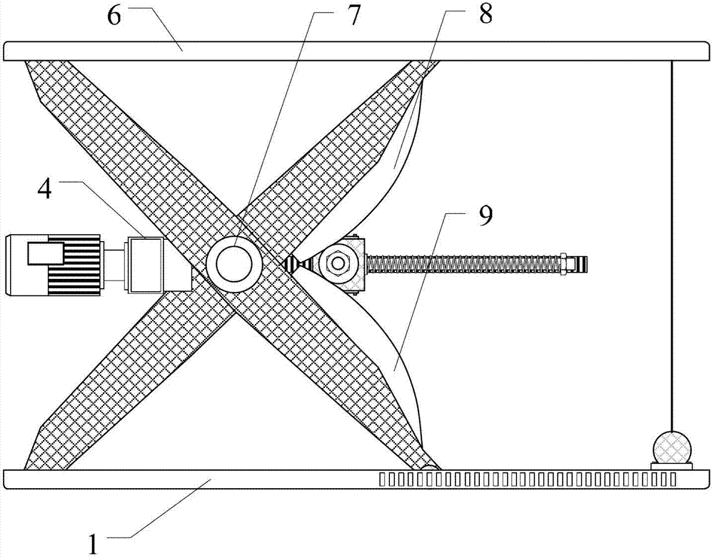
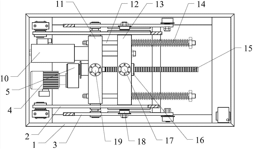
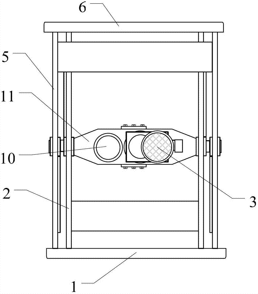
[0014] Such as Figure 1~Figure 3 As shown, the electric lifting platform of the present invention is mainly composed of a base 1, an upper table 6, a scissors mechanism, a screw drive mechanism and a supporting electric control system; the scissors mechanism has two groups, and the two groups of scissors mechanisms Symmetrically arranged on both sides of the electric lifting platform; each set of scissors mechanism is composed of an inner scissors arm 2 and an outer scissors arm 5, and the inner scissors arm 2 and the outer scissors arm 5 are mutually connected by a pin 7 in the middle. Hinged: the lower end of the inner scissor arm 2 is hinged with the base 1, the upper end of the inner scissor arm 2 is supported on the upper table 6 by supporting wheels, and the upper cam plate 8 is installed above the hinge of the inner scissor arm 2; the outer scissor arm ...


PUM


Abstract

The invention relates to an electric lifting table with a spring balanced design. The electric lifting table comprises a base, an upper tabletop, scissor mechanisms, a lead screw transmission mechanism and an assorted electronic control system, and the lead screw transmission mechanism is arranged between the two scissor mechanisms and comprises a motor, a gearbox, a middle box, a push box, a lead screw, a stroke guide rod and a brake hydraulic cylinder. The electric lifting table is characterized in that a compressed balance spring is arranged on the stroke guide rod. A lead screw transmission mechanism of an existing electric lifting table is reasonably modified, counterweight balance is realized by the compressed balance spring arranged on the stroke guide rod, the balance spring assists the motor to lift up a heavy object when the lifting table ascends, and gravitational potential energy is converted into elastic potential energy to be stored by the balance spring when the lifting table descends, so that purposes of reducing power of the motor and improving integral efficiency are realized.

Description

technical field [0001] The invention relates to an improvement of an electric lifting platform, in particular to an electric lifting platform with a spring balance design. Background technique [0002] In the automobile assembly conveyor line, lifting equipment is often used to lift the car body or the slide carrier to realize the switching of workpieces at different heights. Electric lift table (also called electric scissor lift table, cam type electric lift table) is a commonly used lifting equipment. The electric lifting table usually adopts a screw drive mechanism. The motor in the screw drive mechanism drives the screw rod, and the screw drives the screw nut seat to drive, and the lifting and lowering of the heavy object are realized by squeezing the upper cam plate and the lower cam plate. However, in the actual use process, a large starting current often occurs when lifting heavy objects, and when the motor is in the lowering state, the motor is in the power generati...

Claims


Application Information

Patent Timeline
IPC IPC(8): B66F7/06B66F7/28
Inventor 吴雯龙黄建峡张承良
Owner MIRACLE AUTOMATION ENG CO LTD
Why Eureka
Eureka Blog
Learn More