
Vacuum guide roller

A guide roller and vacuum technology, which is applied in the field of papermaking machinery, can solve the problems of power consumption, high maintenance difficulty, and high value, and achieve the effects of reducing relative motion, reducing power consumption and felt loss, and eliminating sliding friction

Inactive Publication Date: 2012-11-07
郭秀梅
View PDF0 Cites 4 Cited by
  • Summary
  • Abstract
  • Description
  • Claims
  • Application Information

AI Technical Summary

Problems solved by technology

In order to ensure the reliability of the seal between the suction box and the inner wall of the rotating housing, there is a certain contact pressure between the sealing strip of the suction box and the inner wall of the housing, forming sliding friction, and the sealing strip and the inner wall produce a "braking" effect. Overcome the "braking" effect caused by the sealing strip and the inner wall, and keep the linear speed of the outer surface of the shell and the speed of the felt in sync. The existing vacuum rollers are equipped with transmission devices, and the structure is complex
[0004] Compared with the vacuum suction box, the existing vacuum roll eliminates the sliding friction with the felt, and the loss of the felt due to sliding friction can be greatly reduced, but there is slippage between the vacuum roll shell and the sealing strip of the inner suction box Friction requires a certain amount of power, and the sealing strip is a vulnerable part that needs to be replaced and maintained regularly
Due to the complex structure of the existing vacuum roll, the value is high and the maintenance is difficult

Method used


Image

  • Vacuum guide roller
  • Vacuum guide roller

Examples


Embodiment Construction

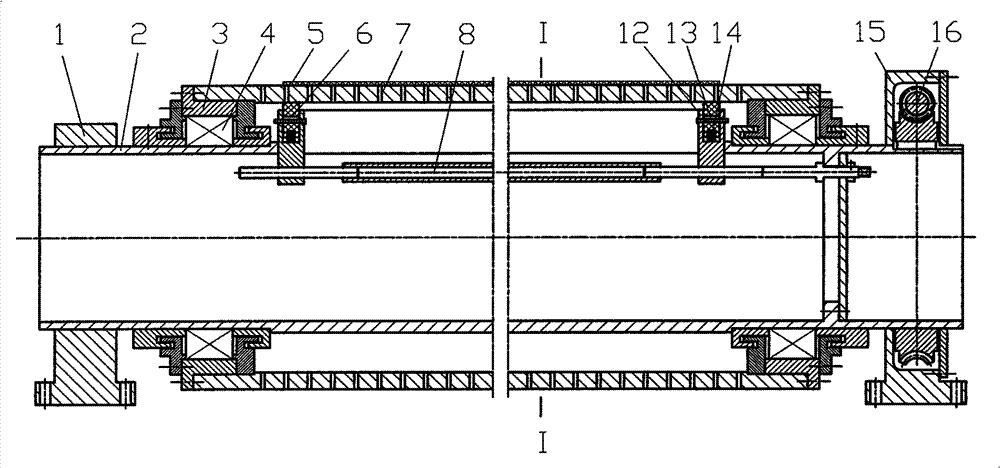
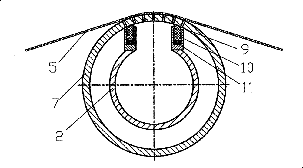
[0012] like figure 1 and figure 2 The specific embodiment of the present invention shown is mainly composed of housing 7, hollow mandrel 2, sealing device, bearing device and other components. Inside and outside, bearing devices are installed at both ends of the shell. The bearing device is mainly composed of bearing chamber 3, bearing 4 and labyrinth seal. Bearing chamber 3 is fixed at both ends of the shell 7. The two ends of the shaft are fixed on the roller support 1 and the support 15, and the worm wheel 16 and the worm are housed in the support 15. The mandrel 2 is a hollow structure in the axial direction, and an elongated hole is processed in the axial direction of the inner part of the housing 7 , and a sealing device is arranged on the elongated opening to contact the inner wall of the housing 7 . There are two types of sealing devices in this specific embodiment, one is end face sealing, and the other is axial sealing. The end face seal is installed at the end p...


PUM


Abstract

The invention relates to the field of paper manufacturing machinery, specifically to a vacuum guide roller. The vacuum guide roller is mainly composed of components such as a shell, a core shaft, sealing devices, bearing devices and so on, wherein the shell is sleeved outside the core shaft; through holes for interior and exterior of the roller shell communicate with each other are processed on the shell; two ends of the shell are equipped with the bearing devices; inside paths of the bearing devices are fixed on the core shaft; a hollow structure is arranged in an axial direction of the shaft, and elongated open holes are processed in part of the axial direction in the shell; and the sealing devices are mounted on the elongated open holes to contact an inner wall of the roller shell. According to the invention, the hollow core shaft sucks, dewaters and cleans carpets, at the same time, the roller shell can be supported by the bearing devices to rotate, relative movement between the roller shell and carpets of paper machines are reduced greatly, and sliding friction in a vacuum box can be removed so as to greatly power consumption and carpet consumption generated by friction of carpets; compared with the existing vacuum roller, the roller can not be equipped with a transmission device so as to simplify device configuration.

Description

technical field [0001] The invention relates to the field of papermaking machinery, in particular to a vacuum guide roller. Background technique [0002] The press part of the paper machine uses a felt to support the operation of the wet paper sheet. In order to ensure the performance and life of the felt, it is necessary to dehydrate and clean the felt in time to remove the sundries accumulated in the felt. The most commonly used press felt cleaning equipment today is the vacuum suction box and the vacuum roll. The vacuum suction box is mainly composed of the box body and the suction box panel. The structure is simple. The surface contact between the suction box panel and the blanket is relatively sliding. Under the suction of the vacuum pump, there is a large sliding friction between the suction box panel and the blanket. Force requires a large power consumption to overcome these friction forces, and the existence of sliding friction also leads to rapid wear of the felt. ...

Claims


Application Information

Patent Timeline
Patent Type & Authority Applications(China)
IPC IPC(8): D21F3/10
Inventor 郭秀梅
Owner 郭秀梅
Learn More