Bidirectional inflow whirling current type shaft facility for flood discharge and energy dissipation in dam

A swirl type and vertical shaft technology, which is applied in the field of discharge and energy dissipation facilities of two-way inflow swirl type vertical shaft in the dam, can solve the problems of strong shaft vibration, difficult wall aeration, small discharge flow, etc., and increase energy dissipation efficiency , Avoid cavitation cavitation, increase the effect of discharge capacity

Inactive Publication Date: 2012-11-07
NORTH CHINA UNIV OF WATER RESOURCES & ELECTRIC POWER
View PDF5 Cites 13 Cited by
  • Summary
  • Abstract
  • Description
  • Claims
  • Application Information

AI Technical Summary

Problems solved by technology

[0003] In view of the above situation, in order to solve the problem of difficult layout of flood discharge and energy dissipation facilities for high dams (high dams above 200m), and to overcome the deficiencies and shortcomings of traditional shaft energy dissipation equipment, the purpose of the present invention is to provide a two-way inflow swirl type in the dam. Shaft discharge and energy dissipation facilities to solve the problems of small discharge flow, low energy dissipation rate, difficult wall aeration, and strong shaft vibration in traditional swirling shafts with high water head and large flow rate

Method used


Image

  • Bidirectional inflow whirling current type shaft facility for flood discharge and energy dissipation in dam
  • Bidirectional inflow whirling current type shaft facility for flood discharge and energy dissipation in dam
  • Bidirectional inflow whirling current type shaft facility for flood discharge and energy dissipation in dam

Examples


Embodiment 1

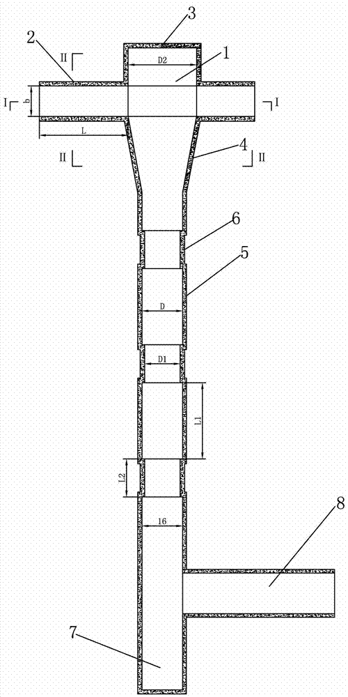
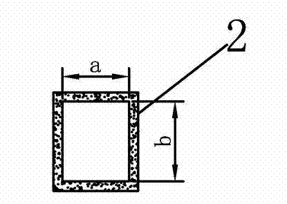
[0016] Example 1: When the flow rate is ≤25m / s and the flow rate is 2000~3000m 3 Under the condition of / s, the diameter of the shaft is D=16m, the section width of the water diversion channel is a=10m, and the height is b=12m.

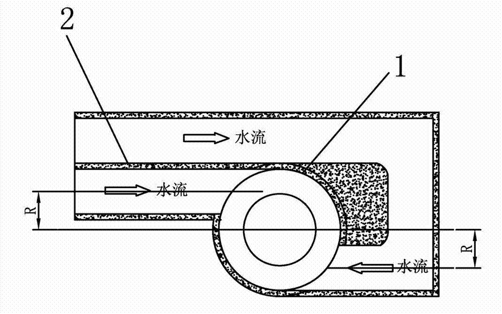
[0017] In general, the larger the eccentricity R, the better, because the larger the eccentricity, the larger the momentum distance of the water flow in the aqueduct to the shaft axis, the more fully the rotation of the water flow in the vortex chamber, and the higher the energy dissipation rate of the swirl shaft system , and the flow pattern will be better, but this often contradicts the width of the high dam. Through theoretical analysis and model tests, the eccentricity R=8.5m;

[0018] According to the test, the diameter of the vortex chamber is D2=27m, the diameter of the air hole is 0.8m, the gradient section is the connection between the vortex chamber and the shaft, and the height is 30m;

[0019] This energy dissipation facility requires a ...


PUM


Abstract

The invention relates to a bidirectional inflow whirling current type shaft facility for flood discharge and energy dissipation in a dam, and aims to solve the problems of small flood discharge volume, low energy dissipation efficiency, difficult aeration of wall surfaces and strong shaft vibration of the existing whirling current shafts in high dams with high water head and flow. A volute chamber is communicated with feed canals through a water inlet on the volute chamber, water outlets of the two feed canals are symmetrically arranged on left and right sides of the volute chamber in an opposite direction, currents entering into the volute chamber from the two feed canals form a 180-degree included angle, the volute chamber is provided with an air vent at the upper end and a transition section at the lower end, a shaft section is connected to the lower end of the transition section and provided with a plurality of sections of hole blocking bodies which are arranged at an interval, a water pillow pool is arranged at the bottom of the shaft section, and a water outlet section communicating with the shaft section is arranged at the upper end of the water pillow pool. According to the shaft facility, the water inlets of the volute chamber are bidirectional and form 180 degrees so as to increase the flood discharge capacity; and the shaft is designed into a whirling current type energy dissipater provided with hole blocking bodies arranged at an interval so as to increase the energy dissipation efficiency of the currents, avoid cavitation damage and cavitation problems of the existing whirling current shafts, and reduce the shaft vibration simultaneously.

Description

technical field [0001] The invention relates to a swirl shaft in a water conservancy and hydropower project, in particular to a bidirectional flow-inflow swirl type shaft discharge and energy dissipation facility in a dam. Background technique [0002] There are many high dams under construction or to be constructed in China, especially dams with a height greater than 200m, which are basically built in deep mountains and canyons, where the mountains are high and the valleys are deep. The problem of flood discharge and energy dissipation is very prominent, especially the problems of discharge, energy dissipation, cavitation, cavitation, turbulent vibration and other problems of discharge structures, which are difficult to be solved urgently; swirl shaft is a new type of flood discharge and energy dissipation Facilities, the diversion channel of the swirling flow internal energy dissipator and the shaft discharge channel are not on the same longitudinal axis. Since the water f...

Claims


Application Information

Patent Timeline
Patent Type & Authority Applications(China)
IPC IPC(8): E02B8/06
Inventor 张先起徐存东孙东坡韩立炜张英克刘慧卿张宏洋
Owner NORTH CHINA UNIV OF WATER RESOURCES & ELECTRIC POWER
Why Eureka
Try Eureka