Connecting shaft structure of external work output connection device of turbine expansion engine

A turbo expander and output connection technology, which is applied to the sealing of the engine, mechanical equipment, engine components, etc., can solve problems that have not been seen in patent and non-patent literature

Inactive Publication Date: 2012-11-07
联优机械(常熟)有限公司
View PDF13 Cites 7 Cited by
  • Summary
  • Abstract
  • Description
  • Claims
  • Application Information

AI Technical Summary

Problems solved by technology

However, in the process of lubricating the bearing sleeve used to support the connecting shaft, there is often a problem that the lubricating oil spreads toward the end of the connecting shaft along the fit gap between the connecting shaft and the bearing sleeve, and the connection between the connecting shaft and the expander As far as one end of the connection is concerned, the lubricating oil seeping from the end of the connecting shaft will pollute the air supply system in the air chamber of the expander; as for the connecting shaft and the matching equipment such as the aforementioned generator, blower, water pump, supercharger For one end of transmission connections such as oil brakes, oil brakes, etc., the lubricating oil leaking from the end of the connecting shaft will pollute the matching equipment
And the leakage of lubricating oil will also affect the lubrication effect of the bearing sleeve and waste lubricating oil
[0005] In order to solve the above problems, the existing technology usually pays attention to the cooperation effect between the sealing sleeve arranged in the sealing ring seat and the connecting shaft and the sealing sleeve material, but practice has proved that it can only play the role of getting twice the result with half the effort
[0006] Therefore, how to find a reasonable balance between sealing and lubrication has become a technical problem that the industry has been paying attention to for a long time and expects to be solved at an early date. There is no technical inspiration that can be used for reference in both patent and non-patent literature. For this reason, the applicant has made protracted research and attempts, and finally found a solution to the problem. The technical solution to be introduced below is based on this background generated under

Method used


Image

  • Connecting shaft structure of external work output connection device of turbine expansion engine
  • Connecting shaft structure of external work output connection device of turbine expansion engine
  • Connecting shaft structure of external work output connection device of turbine expansion engine

Examples


Embodiment

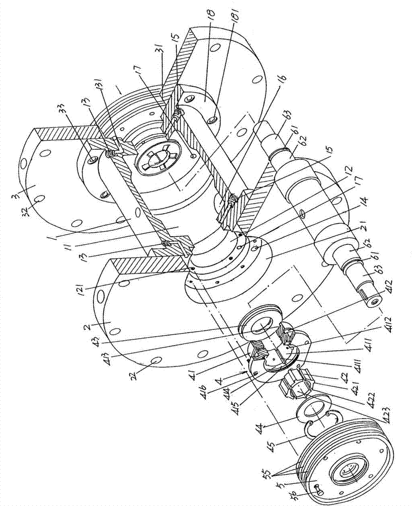
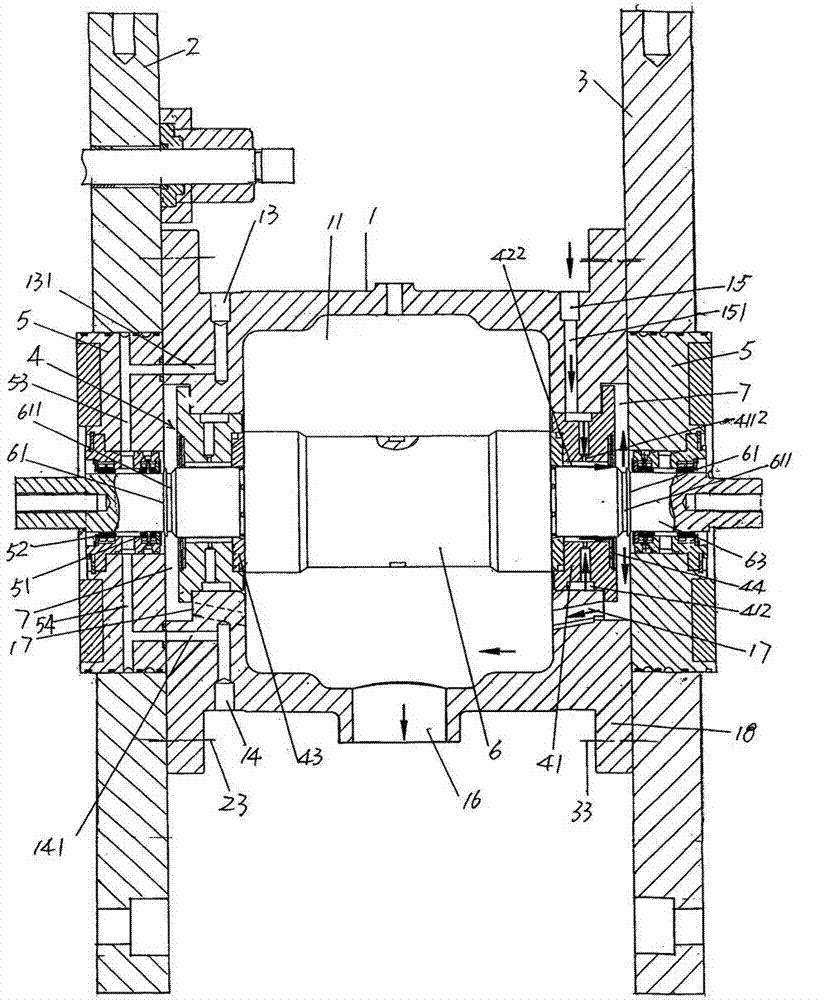
[0019] See figure 1 and figure 2 , a connection sleeve 1 of the external power output connection device of the turbo expander is given. The two ends of the connection sleeve 1, namely the left and right ends, are respectively expanded with a fixed flange edge 18, and each fixed flange A group of flange fixing holes 181 are provided at intervals on the side 18 . An air inlet 13 is provided at both ends of the connecting sleeve 1 and near the corresponding fixed flange edge 18 respectively. At both ends of one side, the pressure air or compressed air from the air source device such as air compressor or booster pump is introduced into the air inlet 13 through the pipeline, and each air inlet 13 has a The air-leading channel 131 is directed toward the sealing ring seat 5 which will be described below, that is to say, the leading air channel 131 extends in the direction of the sealing ring seat 5 . Also, on the connection sleeve 1 and at both ends of the downward position i...


PUM


Abstract

The invention belongs to the technical field of low-temperature equipment, and discloses a connecting shaft structure of an external work output connection device of a turbine expansion engine. The external work output connection device of the turbine expansion engine includes a connecting sleeve, which provided with a sleeve cavity and of which connecting shaft support mechanism cavities formed at the middle parts at the two ends respectively, a left flange plate, a right flange plate, a pair of connecting shaft support mechanisms, and a pair of seal ring seats. The connecting shaft structure includes a connecting shaft supported on the connecting shaft support mechanisms, wherein air inlets are formed in the connecting sleeve and provided with inlet channels; return-air holes are formed in the connecting sleeve; oil inlet holes are formed at the two ends of the connecting sleeve and provided with oil inlet channels; a return-oil hole is formed on one side of the connecting sleeve; oil gaps are formed between the connecting shaft support mechanisms and the seal ring seats; and the two ends of the connecting shaft form a seal gasket matching section. The connecting shaft structure is characterized in that an oil slinger is formed on the connecting shaft and forms an oil throwing groove with one end of the bearing sleeve matching section, and has the advantages that the lubrication and sealing effects are integrated.

Description

technical field [0001] The invention belongs to the technical field of cryogenic equipment, and in particular relates to a connection shaft structure of an external power output connection device of a turbo expander. Background technique [0002] Expanders are usually divided into two types according to their movement mode and structure: one is piston expander; the other is turbo expander. Compared with the piston expander, the turbo expander has the characteristics of large flow, simple structure, small volume, high efficiency and long operation period, so it is widely used in various cryogenic equipment. [0003] As is well known in the industry, a turbo expander is a machine that transfers energy through changes in the speed of gas expansion. The energy transferred is also called external work, usually through the matching equipment connected to it, such as a generator that is not limited , blower, water pump, supercharger, oil brake, etc. There is no lack of technical ...

Claims


Application Information

Patent Timeline
Patent Type & Authority Applications(China)
IPC IPC(8): F01D25/18F16J15/16
Inventor 陈文政杨仁泓
Owner 联优机械(常熟)有限公司
Why Eureka
Try Eureka