Light source module and optical lens thereof

An optical lens and light source module technology, which is applied to lighting devices, lighting device parts, refractors, etc., can solve the problems of incomplete screening, concentrated emitted light, and poor diffusion effects, and achieves power saving, structural Thin and light, the effect of increasing the speed of startup and response

Inactive Publication Date: 2012-11-07
ASIA OPTICAL CO INC
View PDF6 Cites 5 Cited by
  • Summary
  • Abstract
  • Description
  • Claims
  • Application Information

AI Technical Summary

Problems solved by technology

However, the design of the above-mentioned "asymmetric wide-angle lighting device" is still incomplete. If the light is emitted, it will make its illuminance unable to achieve a better diffusion effect
In addition, the crests and troughs of the wavy surface of the lenticular lens array 320 are curved, which will also result in the concentration of the emitted light and poor diffusion effect
[0009] Therefore, it can be seen from the above that the design of the known light source module and its optical lens still fails to meet the requirements, and there is room for improvement.

Method used


Image

  • Light source module and optical lens thereof
  • Light source module and optical lens thereof
  • Light source module and optical lens thereof

Examples


Embodiment Construction

[0024] In order to illustrate the present invention more clearly, preferred embodiments are given and described in detail with accompanying drawings as follows.

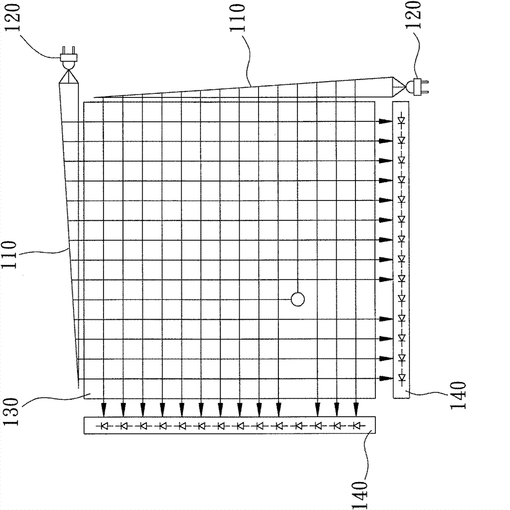
[0025] see Figure 5 The light source module 1 of the present invention can be used for the light source supply of the photosensitive touch panel, and the light source module 1 includes the luminous body 10 and the optical lens 20 in sequence from the light source side to the object side. in:

[0026] In this embodiment, the illuminant 10 is a laser light module, which is used to generate laser light in the direction of the object side, but it is not limited thereto, and light-emitting diodes (LEDs), light bulbs, lamp tubes, or other light-emitting devices can also be used. body instead.

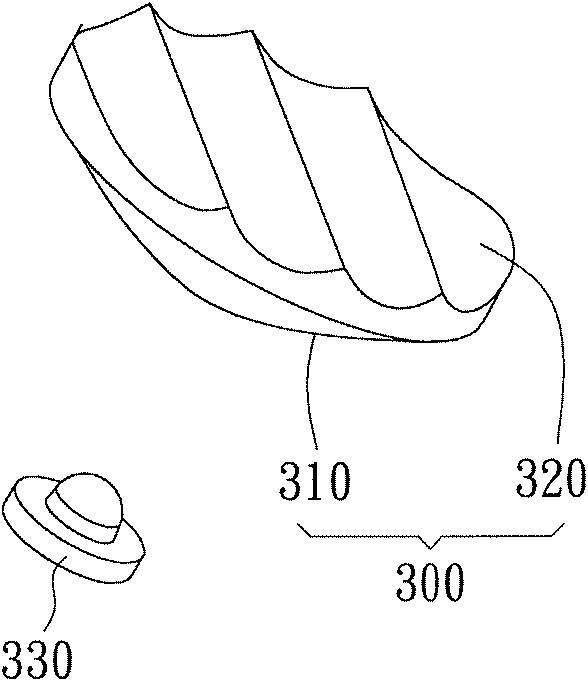
[0027] The optical lens 20 is a plastic lens produced by integral molding through mold injection. The optical lens 20 has a collimating surface 21 , a first plane 22 , a wavy surface 23 and a second plane 24 in sequence from the...


PUM


Abstract

The invention relates to a light source module and an optical lens of the light source module. The light source module comprises lighting bodies from a light source side to an object side in sequence and an optical lens, wherein the lighting bodies are used for generating light rays towards the direction of the object side; the optical lens is provided with a collimation plane, a first plane, a corrugated surface and a second plane which are sequenced from the light source side to the object side, so that the light rays generated by the lighting bodies enter the optical lens from the collimation plane and shoot out from the first plane, then enter the optical lens again through the corrugated surface, and finally shoot out from the second plane to form the collimated and linear illumination.

Description

technical field [0001] The present invention is related to optics, and more specifically refers to a light source module and an optical lens thereof capable of changing the light pattern to collimate and form a line. Background technique [0002] With the advancement of technology, touch panels and touch sensing systems that allow people to directly interact with images are becoming more and more popular. Most of the common touch panels on the market are resistive and capacitive. Among them, The resistive type changes the voltage of the pressed part by pressing the screen to determine the pressed position. However, the resistive type screen must be pressed to sense, so that the surface cannot be made of scratch-resistant hard material, which will cause it to be worn and damaged. The probability of damage increases, and continuous pressing will also easily cause the screen to respond slowly, and there will be a sense of stagnation in use. The capacitive screen uses the metho...

Claims


Application Information

Patent Timeline
Patent Type & Authority Applications(China)
IPC IPC(8): F21V5/04
Inventor 刘华唐王锦祥
Owner ASIA OPTICAL CO INC
Why Eureka
Try Eureka