

Electrode dryer and method for drying electrode
A dryer and electrode technology, which is applied to battery electrodes, progressive dryers, drying, etc., can solve problems such as uneven coating, bending of electrode sheets, and wrinkling of electrode substrates, etc., to achieve stable and uniform electrodes, Reduces uneven coating and prevents sagging
- Summary
- Abstract
- Description
- Claims
- Application Information
AI Technical Summary
Problems solved by technology
Method used
Image

Examples
Embodiment 1
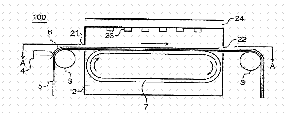
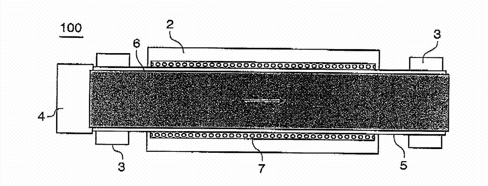
[0030] Figure 1A and Figure 1B is a schematic configuration diagram of the electrode dryer 100 according to Embodiment 1. specifically, Figure 1A is a side view of the electrode dryer 100, and Figure 1B is along Figure 1A The view taken by the line A-A. The electrode dryer 100 mainly includes a drying oven 2 , a backup roll 3 , a coater 4 and a mounting member 7 . The electrode dryer 100 is a device that dries the strip-shaped electrode substrate 5 coated with the electrode slurry 6 as a coating material by the coater 4 while conveying the electrode substrate 5 .
[0031] The drying oven 2 is a box having openings at predetermined positions in opposite sides. The electrode substrate 5 coated with the electrode slurry 6 on one surface passes through one side of the drying furnace 2 ( Figure 1A The inlet 21 provided on the left side in ) is introduced into the drying furnace 2, passes through a predetermined drying process in the drying furnace 2, and then is transporte...
Embodiment 2
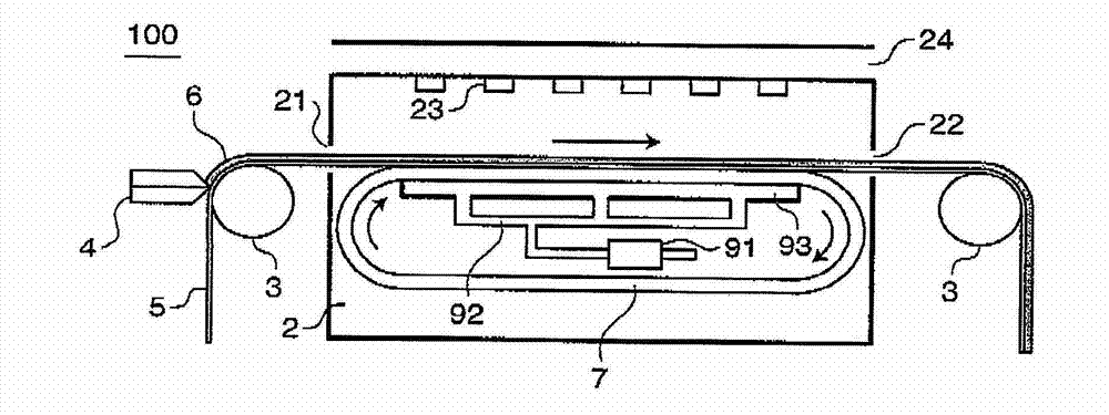
[0049] Next, Embodiment 2 will be described. Embodiment 2 has the same general configuration as Embodiment 1 except for the shape of the mounting member.
[0050] image 3 is a schematic configuration diagram of the electrode dryer 200 according to Embodiment 2 seen from the side. For example, the mounting member 8 is composed of a plurality of metal rollers 81 arranged planarly, with the rotation axes of the plurality of metal rollers 81 oriented in the same direction. The number of metal rollers 81 can be appropriately determined according to the conditions of the electrode base material 5 to be conveyed.
[0051] Figure 4 is a diagram illustrating the shape of each metal roller 81 . In view of the fact that an excessively large radius will result in a large gap between the electrode substrate 5 and the serially connected metal rollers 81, the electrode substrate 5 cannot be stably held, the radius of the metal rollers 81 can be determined, but this depends on the trans...
Embodiment 3
[0055] Next, Embodiment 3 will be described. Embodiment 3 has the same general configuration as Embodiment 2 except for the shape of the mounting member.
[0056] Figure 5 is a schematic configuration diagram of the electrode dryer 300 according to Embodiment 3 seen from the side. For example, the mounting member 5 is made of a metal plate. Preferably, the metal plate has a planar surface and has a width equal to or greater than that of the electrode base material 5 in a direction perpendicular to the transport direction of the electrode base material 5 . Since the flat surface having a width equal to or greater than the base material 5 allows the electrode base material 5 to be held stably, the electrode base material 5 is prevented from sagging or shaking due to hot air during drying, and is prevented from having unevenness as a result. Apply. The mounting member 5 may also have the above-mentioned suction mechanism.
[0057] As described above, the electrode base mate...
PUM
 Abstract
Description
Claims
Application Information