Driving device

一种驱动装置、机动车的技术,应用在传动装置、动力装置、差速传动装置等方向,能够解决安置问题等问题,达到大设计、驱动力矩高的效果

Active Publication Date: 2012-11-14
AUDI AG
View PDF6 Cites 5 Cited by
  • Summary
  • Abstract
  • Description
  • Claims
  • Application Information

AI Technical Summary

Problems solved by technology

The placement of the electric machine in the motor vehicle can cause problems if the electric machine is to have high torque or high drive power

Method used


Image

  • Driving device
  • Driving device

Examples


Embodiment Construction

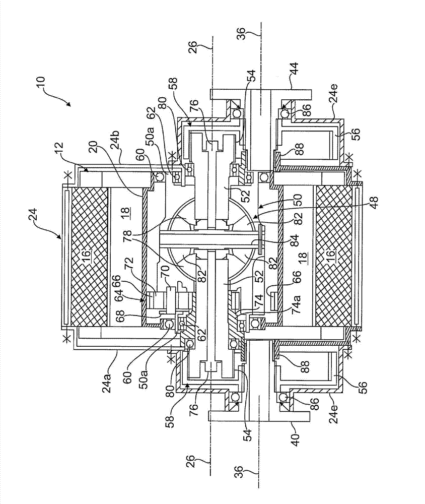
[0017] figure 1 10 marks a drive for an electrically driven axle of a motor vehicle (for example, a front axle or a rear axle), said drive being essentially composed of an electric motor 12 , a planetary gear 64 as an integrated transmission mechanism and also integrated in the motor Conical wheel differential 48 in 12 forms.

[0018] In a manner known per se, the drive motor 12 , which has an annular stator 16 and an annular drive hollow shaft 20 , can also be converted into a generator in the braking or coasting mode of the motor vehicle. on the rotor 18. The drive hollow shaft 20 is mounted via rolling bearings 60 in a manner that will be described rotatably about a first axis of rotation 26 in the housing walls 24 a , 24 b of the housing 24 of the electric motor 12 , which thus defines the electric motor 12 . center of".

[0019] The output of the bridge cone 78 of the differential 48 is on the intermediate shaft 52 which is rotatably supported in the housing walls 24a,...


PUM


Abstract

The invention relates to a driving device, used for a wheel of a motor vehicle having the aid of a motor and driven by a differential mechanism; wherein the motor possessing rotors and a stator drives the input element of the differential mechanism, and the output element of the differential mechanism is outputted to the wheel of the motor vehicle via an output shaft. In order to realize a structure which is compact in structure and favorable in gear ratio, the driving device is provided. The annular rotors (18) of the motor (12) are outputted to the input element (50) of the differential mechanism (48) via variable-speed control mechanisms (64, 64'), and the variable-speed control mechanisms (64, 64') and the differential mechanism (48) are integrated in the rotors (18, 20).

Description

technical field [0001] The invention relates to a drive device according to the preamble of claim 1 for wheels of a motor vehicle driven via a differential by means of an electric motor. Background technique [0002] It is already known in electrically driven motor vehicles or hybrid drives that the axles of the motor vehicle are driven by means of an electric motor or an electric machine (which can also be converted into a generator in braking mode) via the usual differential gear. The placement of the electric machine in the motor vehicle can cause problems if the electric machine is to have a high torque or a high drive power. Contents of the invention [0003] It is an object of the invention to provide a drive device of the type mentioned at the outset, by means of which a relatively bulky electric motor or an electric motor can be mounted in an advantageous configuration and with a large degree of structural freedom. [0004] This object is achieved according to the...

Claims


Application Information

Patent Timeline
Patent Type & Authority Applications(China)
IPC IPC(8): B60K17/16B60K17/12
CPCB60K17/12B60K17/165F16H48/06B60K17/16B60K7/0007
Inventor J·梅尔克
Owner AUDI AG
Why Eureka
Try Eureka