Collecting pipe and parallel flow evaporator using same

A collecting tube and evaporator technology, which is applied in the field of parallel flow evaporators, can solve the problems of low product welding pass rate, high production cost, and affecting product performance, and achieve the goal of improving universality, saving installation man-hours, and low manufacturing costs Effect

Inactive Publication Date: 2012-11-14
SONGZ AUTOMOBILE AIR CONDITIONING
View PDF4 Cites 7 Cited by
  • Summary
  • Abstract
  • Description
  • Claims
  • Application Information

AI Technical Summary

Problems solved by technology

[0007] The existing headers of parallel flow evaporators have the following disadvantages: if damping baffles are installed in the headers, it is necessary to open a plurality of grooves on the headers to match the damping baffles. The multiple cooperation between the plate and the header is prone to refrigerant leakage, which affects the performance of the product, and because the position of the damping partition has certain requirements, during assembly, because there are multiple slots, the worker may place the damping partition incorrectly. The position of the board affects the product performance; and the production process is complicated, the process is cumbersome, the product welding pass rate is low, and the production cost is high

Method used


Image

  • Collecting pipe and parallel flow evaporator using same
  • Collecting pipe and parallel flow evaporator using same
  • Collecting pipe and parallel flow evaporator using same

Examples


Embodiment Construction

[0029] The specific implementation of the header provided by the present invention and the parallel flow evaporator using the header will be described in detail below with reference to the accompanying drawings.

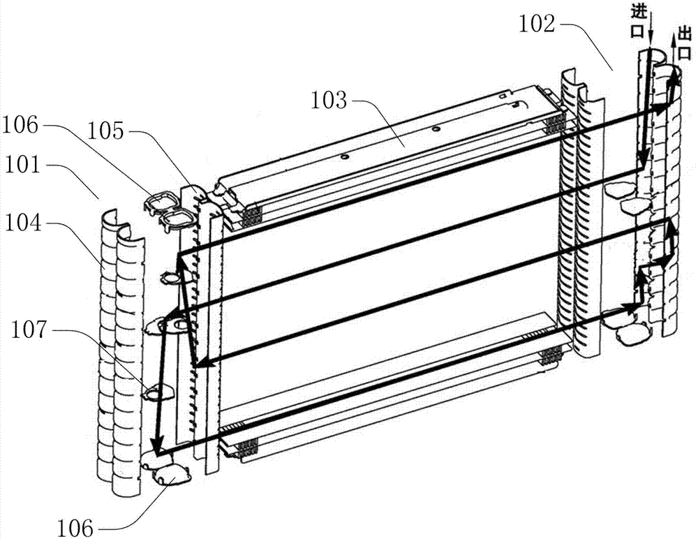
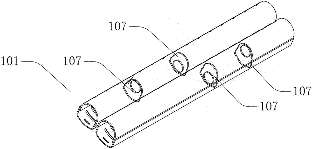
[0030] Figure 2A Shown is the perspective schematic view of the structure of the collector of the present invention, Figure 2B shown as Figure 2A A schematic cross-sectional view along the A-A direction. see Figure 2A and Figure 2B As shown, the header 1 includes a first lumen 2 and a second lumen 3 . The first lumen 2 and the second lumen 3 are parallel to each other, and the axes of the first lumen 2 and the second lumen 3 are parallel to the length direction of the header 1 . In this embodiment, preferably, the first lumen 2 and the second lumen 3 are integrally formed, for example, an "8"-shaped structure integrally formed, and the upper and lower parts of the "8"-shaped structure form a header The first lumen 2 and the second lumen 3 of 1. The one-pi...


PUM


Abstract

The invention provides a collecting pipe and a parallel flow evaporator using the same. The collecting pipe comprises a first pipe cavity, a second pipe cavity, a first seal cover and a second seal cover, wherein the first pipe cavity is parallel to the second pipe cavity, the axial directions of the first pipe cavity and the second pipe cavity are parallel to the length direction of the collecting pipe, the first seal cover is positioned on one end of the collecting pipe, and the second seal cover is positioned on the other end of the collecting pipe. The collecting pipe also comprises a first positioning plate, a second positioning plate, a first perforated plate and a second perforated plate which are arranged in the collecting pipe, wherein the first positioning plate and the second positioning plate are respectively arranged on the middle parts of the first pipe cavity and the second pipe cavity; one end of the first perforated plate is connected with the first seal cover, the other end of the first perforated plate is inserted into an opening hole of the first positioning plate, one end of the second perforated plate is inserted into an opening hole of the second positioning plate, the other end of the second perforated plate is connected with the second seal cover, and the first perforated plate and the second perforated plate are of a U-shaped structure and are provided with a plurality of holes distributed along the length direction. The collecting pipe has the advantages of simple structure, convenience in installation, installation labor-hour saving, low manufacturing cost and high generality degree.

Description

technical field [0001] The invention relates to the technical field of automobile air conditioners, in particular to a collector for automobile air conditioners and a parallel flow evaporator using the collector. Background technique [0002] At present, the space for installing air conditioners in automobiles is limited, and the size of the air conditioner has strict requirements. Therefore, the evaporator of the automobile air conditioner is required to have the characteristics of high cooling efficiency, small size, and light weight. Therefore, the thickness of the evaporator core is getting more and more thinner. When the thickness of the evaporator core is reduced to a certain extent, the original stacked structure can no longer meet the performance requirements of the air conditioner, so a parallel flow evaporator appears. [0003] Figure 1A Shown is an exploded schematic diagram of the structure of a parallel flow evaporator in the prior art. see Figure 1A As show...

Claims


Application Information

Patent Timeline
Patent Type & Authority Applications(China)
IPC IPC(8): F28F9/02F25B39/02
Inventor 黄国强陈树荫许建国王永军
Owner SONGZ AUTOMOBILE AIR CONDITIONING
Why Eureka
Try Eureka