Optical transmitting and receiving integral single-fiber bidirectional device and assembling fixture thereof

A single-fiber bidirectional, optical transceiver technology, applied in the field of laser communication, can solve the problems of difficult control of receiving sensitivity, complex receiving optical path, and high difficulty in production process, and achieve the effect of simplified structure and processing technology, and low processing cost.

Inactive Publication Date: 2012-11-14
江苏飞格光电有限公司
View PDF3 Cites 6 Cited by
  • Summary
  • Abstract
  • Description
  • Claims
  • Application Information

AI Technical Summary

Problems solved by technology

[0002] At present, single-fiber bidirectional communication technology has been widely used in the field of optical communication. As the core component of single-fiber bidirectional optical communication --- optical transceiver integrated single-fiber bidirectional device also has a variety of design schemes, usually optical transceiver integrated The single-fiber bidirectional device has a square bracket, and the ferrule seat with the ceramic ferrule is installed in the square bracket. The transmitting light hole and the receiving light hole are set in different directions of the square bracket, and the laser and the light receiving detector are installed respectively. The square bracket It is also necessary to set a 45-degree beam splitter and a 0-degree filter on the optical path inside, but in most solutions, the 45-degree beam splitter and the 0-degree filter are fixed on a square bracket or a detector. Disadvantages such as high production process difficulty, complex receiving optical path, difficult control of receiving sensitivity, etc.

Method used


Image

  • Optical transmitting and receiving integral single-fiber bidirectional device and assembling fixture thereof
  • Optical transmitting and receiving integral single-fiber bidirectional device and assembling fixture thereof
  • Optical transmitting and receiving integral single-fiber bidirectional device and assembling fixture thereof

Examples


Embodiment Construction

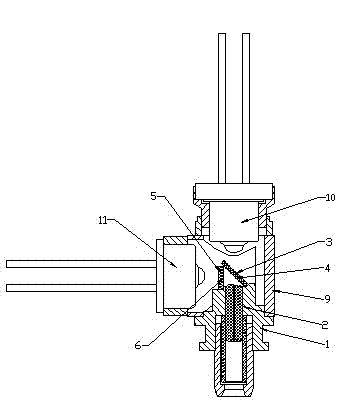
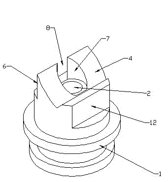
[0012] Such as figure 1 , figure 2 As shown, the optical transceiver integrated single-fiber bidirectional device includes a ferrule seat 1, a ceramic ferrule, a ceramic sleeve and a sleeve seat are installed in the center hole 2 of the ferrule seat in an interference manner, and the ferrule seat The upper end is provided with a 45-degree plane 4 for placing a 45-degree beam splitter 3 and a 0-degree plane 6 for placing a 0-degree filter 5; the upper end of the center hole of the ferrule seat has a section of diameter-enlarged light-through hole 7 , the light hole intersects with the 0-degree plane to form a side light-through gap 8, so that the received optical signal transmitted by the ferrule in the single-fiber bidirectional device can pass through the light-through gap after being reflected by the 45-degree beam splitter and Enter the detector; the 45-degree beam splitter 3 and the 0-degree filter 5 are bonded and fixed on the 45-degree plane 4 and the 0-degree plane 6 ...


PUM


Abstract

The invention relates to the technical field of laser communication, in particular to an optical transmitting and receiving integral single-fiber bidirectional device used for the optical communication and an assembling fixture thereof. The center hole of the mortise holder of the optical transmitting and receiving integral single-fiber bidirectional device is cooperatively provided with a ceramic mortise, a ceramic sleeve and a sleeve holder in an interference mode; the upper end of the mortise holder is provided with a 45-degree plane and a 0-degree plane, wherein the 45-degree plane is used for arranging a 45-degree light-splitting sheet, and the 0-degree plane is used for arranging a 0-degree light filter; the upper end of the center hole of the mortise holder is provided with a light emitting hole of which one section of the diameter is enlarged; the light emitting hole and the 0-degree plane are cross to form a side-surface light emitting gap; the 45-degree light splitting sheet and the 0-degree light filter are respectively bonded and fixedly arranged on the 45-degree plane and the 0-degree plane; and the mortise holder with the 45-degree light splitting sheet and the 0-degree light filter is axially inserted into a square bracket. The optical transmitting and receiving integral single-fiber bidirectional device and the assembling fixture have the advantages of simple structure, low manufacture technology difficulty and low cost, and the emitted light power or the receiving sensitivity is easy to couple.

Description

technical field [0001] The invention relates to the technical field of laser communication, in particular to an optical transceiver integrated single-fiber bidirectional device for optical communication and an assembly fixture thereof. Background technique [0002] At present, single-fiber bidirectional communication technology has been widely used in the field of optical communication. As the core component of single-fiber bidirectional optical communication --- optical transceiver integrated single-fiber bidirectional device also has a variety of design schemes, usually optical transceiver integrated The single-fiber bidirectional device has a square bracket, and the ferrule seat with the ceramic ferrule is installed in the square bracket. The transmitting light hole and the receiving light hole are set in different directions of the square bracket, and the laser and the light receiving detector are installed respectively. The square bracket It is also necessary to set a 4...

Claims


Application Information

Patent Timeline
Patent Type & Authority Applications(China)
IPC IPC(8): G02B6/42H04B10/24
Inventor 周四海詹敦平徐东进章林强
Owner 江苏飞格光电有限公司
Why Eureka
Try Eureka