Temperature-difference power generation system

A technology of thermoelectric power generation and temperature difference, which is applied in the direction of generators/motors, electrical components, etc., can solve the problems that thermoelectric generators cannot communicate with tap water or well water through pipelines, cannot use thermoelectric generators to generate electricity, and have limited application occasions, etc., to achieve Improve reusability and economy, reduce environmental heat emissions, and improve the effect of reusability

Inactive Publication Date: 2012-11-14
苟仲武
View PDF2 Cites 10 Cited by
  • Summary
  • Abstract
  • Description
  • Claims
  • Application Information

AI Technical Summary

Problems solved by technology

[0005] Therefore, the thermoelectric generator power generation method in the prior art has limited application occasions, and needs to continuously replenish the cold flow medium from the outside world. It cannot be applied in occasions where the cold flow medium supplemented by the outside world cannot be received, that is, there is no external cold source.
For example, in some occasions where the thermoelectric generator needs to be moved, the thermoelectric generator cannot be connected with tap water or well water through the pipeline, so the thermoelectric generator cannot be used to generate electricity

Method used


Image

  • Temperature-difference power generation system
  • Temperature-difference power generation system
  • Temperature-difference power generation system

Examples


Embodiment 1

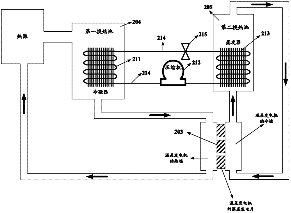
[0052] Referring to FIG. 2 , the thermoelectric power generation system according to Embodiment 1 of the present invention includes: a thermoelectric generator 203 , a heat pump device (not marked in the figure), a first heat exchange pool 204 , and a second heat exchange pool 205 . Wherein, the heat pump device specifically includes: a condenser 211 , a compressor 212 , an evaporator 213 , a refrigerant circulation pipeline 214 , and a throttle valve 215 .

[0053] The condenser 211 is disposed in the first heat exchange pool 204 ; the evaporator 213 is disposed in the second heat exchange pool 205 .

[0054] The hot flow medium flowing out from the heat source passes through the first heat exchange pool 204 and flows through the hot end 203 of the thermoelectric generator. Specifically, one end of the first heat exchange pool 204 is connected to the heat source, and the other end is connected to the inlet of the hot end of the thermoelectric generator 203 . The heat source ...

Embodiment 2

[0068] Furthermore, waste heat can also be recycled for power supply. Another thermoelectric power generation system provided by Embodiment 2 of the present invention can be found in image 3 As shown, it includes: a waste heat accumulation subsystem 301 , a first heat pump device 302 , a high calorific value energy output subsystem 303 , a thermoelectric generator 203 , a third heat exchange pool 305 , and a second heat pump device 304 .

[0069] Wherein, both the first heat pump device 302 and the second heat pump device 304 include a condenser 211 , a compressor 212 , an evaporator 213 , a refrigerant circulation pipeline 214 , and a throttle valve 215 . The functions and working principles of the condenser 211, compressor 212, evaporator 213, refrigerant circulation pipeline 214, and throttle valve 215 of the first heat pump device 302 and the second heat pump device 304 are the same as those of the first heat pump device in the above-mentioned embodiment. I won't repeat ...


PUM


Abstract

The invention discloses a temperature-difference power generation system, which comprises a temperature-difference generator, a hot pump device, a first heat exchange pool and a second heat exchange pool, wherein hot flowing medium flowing out from a hot source flows through the hot end of the temperature-difference generator via the first heat exchange pool; cold flowing medium flowing out from the second heat exchange pool flows through the cold end of the temperature-difference generator to flow back to the second heat exchange pool; a condenser of the hot pump device is arranged in the first heat exchange pool; heat is released to the flowing medium flowing through the first heat exchange pool; and an evaporator of the hot pump device is arranged in the second heat exchange pool to adsorb heat of the flowing medium in the second heat exchange pool. Because the hot pump technology is utilized, the medium on the cold end of the temperature-difference generator is kept at the low-temperature state, and therefore the temperature-difference generator can be applied to occasions which do not need an external cold source. In addition, energy released from the cold end of the temperature-difference generator is recovered and utilized by the hot pump. After certain energy is supplemented, the hot pump is utilized on the hot end of the temperature-difference generator for generating power, and a purpose of reducing thermal discharge is achieved.

Description

technical field [0001] The invention relates to energy-saving and emission-reduction technologies, in particular to a system for recovering waste heat, reducing heat discharge to the environment, and enabling it to output electric energy. Background technique [0002] Although in recent years, with the increasingly prominent energy and environmental crisis and the successful development of a batch of high-performance thermoelectric conversion materials, the research of thermoelectric technology has become a hot spot again. The principle of semiconductor thermoelectric power generation is to combine two different types of thermoelectric conversion materials N and P, and place one end in a high temperature state, and when the other end is opened and given a low temperature, due to the strong thermal excitation at the high temperature end, holes and The electron concentration is also higher than that at the low-temperature end. Driven by this carrier concentration gradient, hol...

Claims


Application Information

Patent Timeline
IPC IPC(8): H02N11/00
Inventor 苟仲武
Owner 苟仲武
Why Eureka
Try Eureka