An electric motor arrangement and method of controlling thereof

A motor and controller technology, which is used in motor generator control, electronic commutation motor control, and DC motor deceleration devices, etc., can solve the problems of high cost and large size of energy transfer resistors, and achieve the effect of effectively controlling short circuits.

Active Publication Date: 2012-11-14
PROTEAN ELECTRIC LIMITED
View PDF4 Cites 6 Cited by
  • Summary
  • Abstract
  • Description
  • Claims
  • Application Information

AI Technical Summary

Problems solved by technology

However, shifting resisto

Method used


Image

  • An electric motor arrangement and method of controlling thereof
  • An electric motor arrangement and method of controlling thereof
  • An electric motor arrangement and method of controlling thereof

Examples


Embodiment Construction

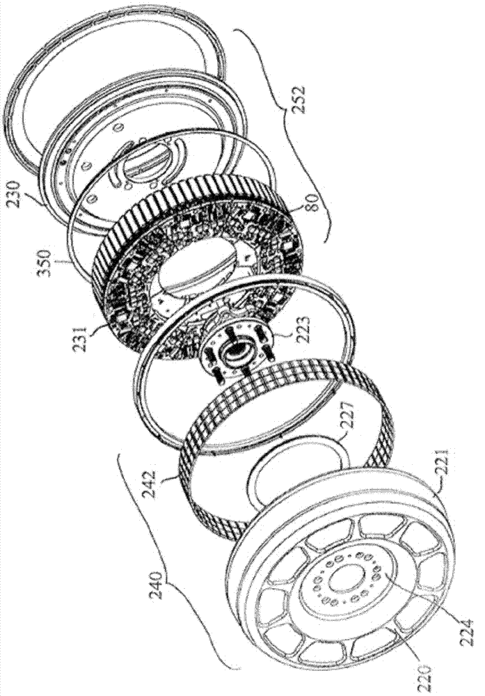
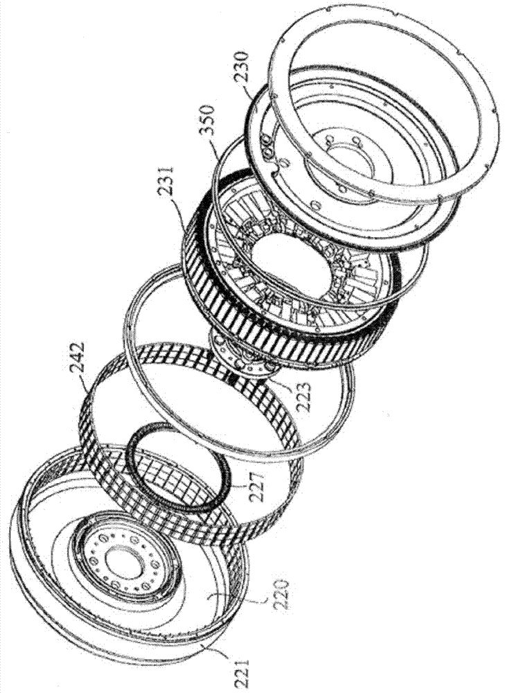
[0024] The specific embodiment described in the present invention is a permanent magnet synchronous motor for use in a wheel, that is, an in-wheel motor. However, the present invention can also be applied to other types of permanent magnet synchronous motors, as is well known to those skilled in the art. This type of electric motor has a set of coils which is part of a stator for mounting to a vehicle, axially surrounded by a rotor with a set of magnets for mounting to a wheel. Furthermore, some aspects of the present invention are applicable to a device having a rotor self-fitted into an axially surrounding coil.

[0025] The physical device of the concrete implementation of the present invention can refer to figure 1 with figure 2 to be best understood. The device may be described as an electric motor with built-in electronics and bearings, or when the device is constructed to accommodate separate wheels, it may also be described as a hub motor or hub drive. However, th...


PUM


Abstract

An electric motor arrangement comprises an electric motor and a controller. The electric motor includes: a stator having a plurality of coil windings, and a rotor having a plurality of permanent magnets. The controller is arranged to control current flow through the plurality of coil windings to generate a braking torque on the rotor. The current is defined by a stator current vector represented in a two co-ordinate time invariant system having a rotating quadrature and direct axis by a quadrature current component and a direct current component, wherein the controller is arranged to vary the quadrature current component and the direct current component so that the input electrical power of the electric motor is greater than or equal to zero.

Description

technical field [0001] The invention relates to an electric motor arrangement, in particular an electric motor arrangement configurable to reduce the current to an energy storage device during regenerative braking of the electric motor. Background technique [0002] Interest in environmentally friendly vehicles is growing, and perhaps unsurprisingly, there is a related growing interest in the use of electric vehicles. [0003] Electric vehicles typically employ electric motors to provide propulsion for the vehicle and regenerative braking for stopping the vehicle. For effective regenerative braking, the rotational motion of a drive wheel connected to an electric motor is converted into electrical energy. This involves the dissipation of kinetic energy, providing a braking force on the drive wheels by applying a braking torque in the opposite direction of rotation of said drive wheels. [0004] The electrical energy generated during regenerative braking causes an electrical...

Claims


Application Information

Patent Timeline
IPC IPC(8): H02P21/00H02P3/14H02K16/00
CPCH02P21/0092B60L15/007B60L2270/145B60L15/025B60L2270/142Y02T10/643H02P6/24B60L2220/44H02P3/18B60L15/2045B60L7/14B60L2220/14H02P21/36Y02T10/64Y02T10/72B60L7/10B60L7/16B60L7/18H02P3/14
Inventor 蒂莫西·约翰·马丁
Owner PROTEAN ELECTRIC LIMITED
Why Eureka
Try Eureka