
Glue filling process for tire pressure monitoring sensor

A tire pressure monitoring and sensor technology, which is applied to the surface coating liquid device, pretreatment surface, coating, etc., can solve the problems of poor control of baking time, increase of product production cost, cost increase, etc., and achieve improvement Glue filling production efficiency, stable and controllable process, and the effect of avoiding air bubbles

Active Publication Date: 2012-11-21
SHANGHAI VEI SHENG AUTO PARTS MFG CO LTD
View PDF4 Cites 6 Cited by
  • Summary
  • Abstract
  • Description
  • Claims
  • Application Information

AI Technical Summary

Problems solved by technology

[0005] 1. During the handling of the product, the adhesive material is easy to overflow the product, resulting in poor appearance of the product and increasing the man-hours for product maintenance
[0006] 2. After the glue is filled, the product is baked in an oven, and the baking time is not easy to control, and there are hidden dangers in product quality
[0007] 3. After the product is baked, bubbles will appear on the surface of the rubber material, and the defect rate and scrap rate will increase, resulting in an increase in cost; the product is baked in an oven, and the quantity of each baking is generally 600-800PCS. If there is an abnormality in the product, it cannot be found in time. Directly lead to a straight rise in the product defect rate or scrap rate, increasing the production cost of the product
[0008] 4. After the product is filled with glue, vacuumize the glued product to achieve the purpose of reducing air bubbles. This will add a new process and increase the manufacturing cost of the product
Vacuuming the glue-filled product poses a product safety hazard

Method used


Image

  • Glue filling process for tire pressure monitoring sensor
  • Glue filling process for tire pressure monitoring sensor

Examples


Embodiment approach

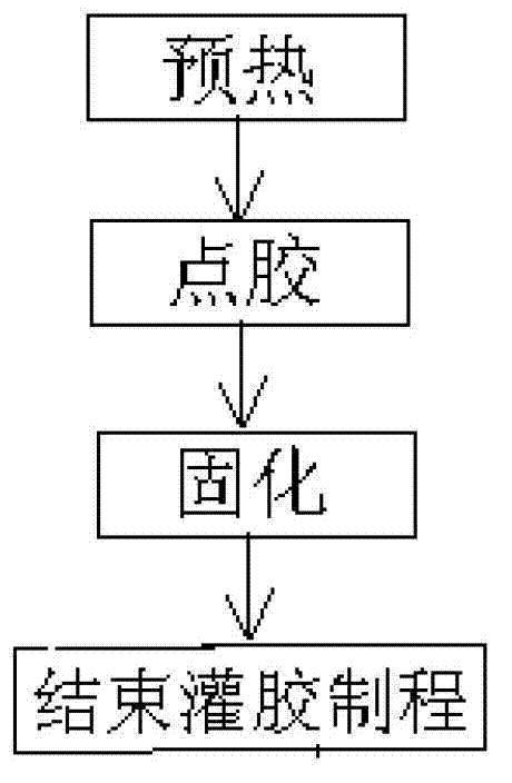
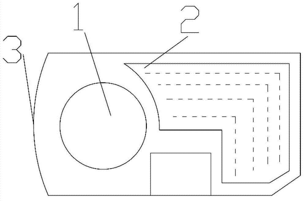
[0029] as attached figure 1 As shown, it is an embodiment of the glue filling process of the tire pressure monitoring sensor of the present invention, a kind of glue filling process of the tire pressure monitoring sensor, as attached figure 2 As shown, the sensor includes a lithium battery 1 used as a power supply, a circuit board 2 and an installation housing 3, and the lithium battery 1 and the circuit board 2 are fixed in the installation housing 3; the glue filling process includes the following steps:

[0030] Step 1: preheating, preheating the sensor, for example, the preheating temperature in this embodiment is 80°C, and the time is 5 minutes;

[0031] Step 2: Vacuumize and preheat the glue material: vacuumize the glue material required for glue filling and preheat the glue material for 30 minutes; the glue material in this embodiment is a high-performance epoxy resin adhesive, more specifically Can be epoxy resin AB glue;

[0032] Step 3: Glue dispensing; place the ...


PUM


Abstract

The invention discloses a glue filling process for a tire pressure monitoring sensor. The sensor comprises a power supply, a circuit board and an installation shell. A process for filling glue into the installation shell after the power supply and the circuit board are fixedly arranged on the installation shell comprises the following steps of: I, preheating: preheating the sensor; II, vacuumizing and preheating a rubber material: vacuumizing the rubber material required by glue filling, and preheating the rubber material; III, dispensing: placing the preheated sensor onto a glue filling stage, and dispensing by using the preheated rubber material; and IV, curing: placing the glue-filled sensor into a reflow soldering furnace for baking and curing to complete an entire glue filling process. The sensor is preheated and the rubber material is vacuumized and preheated before glue filling, and a secondary glue filling method and a way for baking and curing with the reflow soldering furnace are adopted during glue filling, so that the glue filling production efficiency is increased effectively, air bubbles produced in a glue filling process are avoided, an entire process is more stable and controllable, and a procedure is more concise.

Description

technical field [0001] The invention relates to a glue filling process for a product, in particular to a glue filling process for a tire pressure monitoring sensor. Background technique [0002] The tire pressure monitoring sensor (TPMS Sensor) is a sensor installed inside the tire to collect the air pressure and temperature parameters in the tire. The tire pressure monitoring sensor transmits the detected data to the corresponding receiving end through wireless transmission for processing and display. . The tire pressure monitoring sensor usually includes a lithium battery used as a power source, a circuit board integrated with a pressure sensor, a temperature sensor and an acceleration sensor, and an installation case, and the lithium battery and the circuit board are fixed in the installation case. After fixing the lithium battery and the circuit board in the installation housing, it is often necessary to fill the installation housing with glue to ensure that the entire ...

Claims


Application Information

Patent Timeline
IPC IPC(8): B05C5/04B05C5/02B05D3/02
Inventor 尤山泉钱廷钧林东峰陈亚胡提涛
Owner SHANGHAI VEI SHENG AUTO PARTS MFG CO LTD
Learn More