Steel tube traction machine

A tractor and steel pipe technology, applied in the tractor field, can solve the problems of uneven distribution of clamping force, inconvenient change of pipe fitting specifications, poor alignment and adjustment accuracy of clamping force, etc.

Active Publication Date: 2012-11-21
ZHEJIANG SHUANGLIN PLASTIC MACHINERY
View PDF6 Cites 4 Cited by
  • Summary
  • Abstract
  • Description
  • Claims
  • Application Information

AI Technical Summary

Problems solved by technology

As announced on February 8, 1995, the authorized announcement number is 2189016Y, and a double-chain crawler-type steel pipe traction mechanism disclosed in the Chinese patent document entitled "A Metal Thin-walled Pipe Welding and Forming Equipment" includes two upper and lower pairs of The caterpillars are set and rotate in opposite directions, the pressing blocks fixed on the caterpillars and moving with the caterpillars, used to clamp the pipe fittings, and the crawler lifting mechanism; the centering and clamping force adjustment are mainly carried out through the crawler lifting mechanism. The existing problems are : Complex structure, poor centering and clamping force adjustment accuracy, uneven distribution of clamping force, inconvenient change of pipe fitting specifications

Method used


Image

  • Steel tube traction machine
  • Steel tube traction machine
  • Steel tube traction machine

Examples


Embodiment Construction

[0020] The technical solutions of the present invention will be further specifically described below through the embodiments and in conjunction with the accompanying drawings.

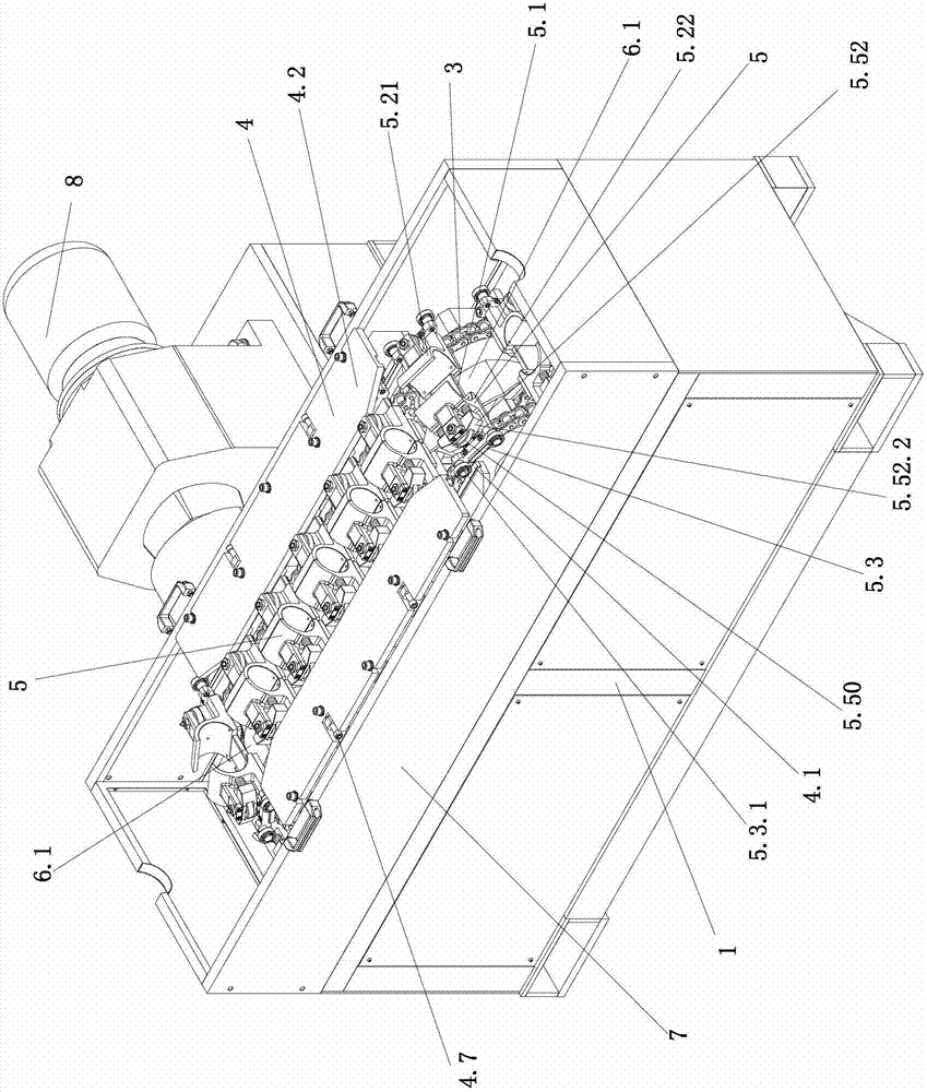
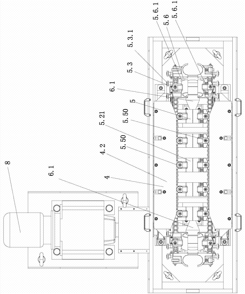
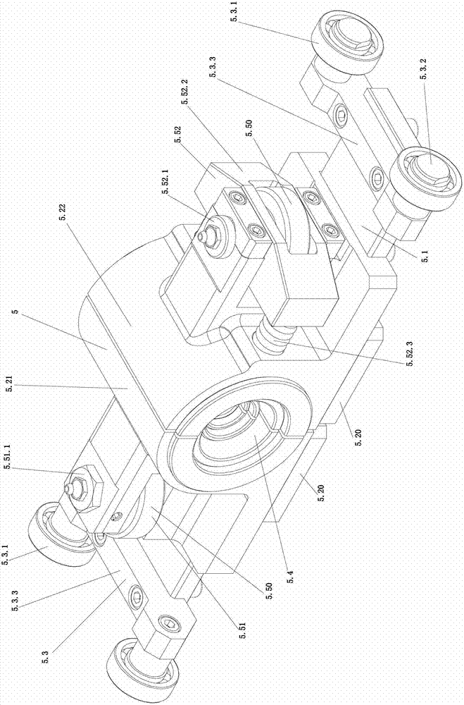
[0021] Such as figure 1 , figure 2 As shown, the present invention includes a frame 1, the main and driven shafts respectively rolling and supported on the left and right ends of the frame 1, the power source system including the motor, the reducer and the electrical control system, facing each other front and back, and rotating in the same direction The chain 3 and the corresponding sprocket wheel, the guide bracket 4, the clamps fixed on the left and right ends of the frame 1 respectively to open the bracket 6 and some chuck parts 5 for clamping pipe fittings, and the protective cover 7; the protective cover 7 It includes the side wall of the protective cover which is detachably connected to the upper end of the lower end of the frame 1 and the protective cover cover which is not shown in the figur...


PUM


Abstract

The invention discloses a steel tube traction machine. The machine comprises a rack, a main drive shaft and a driven shaft, two chains which are arranged opposite to each other in front and at the back, a guide support, a chuck opening support and a plurality of chuck parts, wherein two horizontal guide blocks and two clamping guide plates are arranged opposite to each other in the front and at the back of the guide support; each of the chuck parts comprises a sliding plate, a first chuck base, a second chuck base and a chuck; two ends of the sliding plate are connected fixedly with chain plates of the chains and are provided with a guide roller assembly which is matched with the horizontal guide blocks; the first chuck base and the second chuck base are connected with the sliding plates in a sliding mode opposite to each other in the front and at the back and are provided with a chuck opening roller assembly which is matched with the chuck opening support, an opposite end is provided with a chuck installation portion respectively, and the other end is provided with a first clamping roller assembly and a second clamping roller assembly, which are matched with the clamping guide plates respectively, except the chuck which is matched with a pipe fitting with a maximum specification, a plurality of sub-chucks are overlapped to form the other chucks. The steel tube traction machine relates to the field of manufacture devices of steel-plastic composites pipes and has the advantages of being simple in structure, convenient in centering adjustment, high in accuracy, even in clamping force distribution and convenient in pipe fitting specification conversion.

Description

technical field [0001] The invention relates to the field of manufacturing equipment for steel-plastic composite pipes, in particular to a tractor for straight pipes. Background technique [0002] At present, in the production and manufacture of steel-plastic composite pipes, the vertically opposed double chain crawler-type steel pipe traction mechanism is usually used to draw straight pipes. As announced on February 8, 1995, the authorized announcement number is 2189016Y, and a double-chain crawler-type steel pipe traction mechanism disclosed in the Chinese patent document entitled "A Metal Thin-walled Pipe Welding and Forming Equipment" includes two upper and lower pairs of The caterpillars are set and rotate in opposite directions, the pressing blocks fixed on the caterpillars and moving with the caterpillars, used to clamp the pipe fittings, and the crawler lifting mechanism; the centering and clamping force adjustment are mainly carried out through the crawler lifting m...

Claims


Application Information

Patent Timeline
Patent Type & Authority Applications(China)
IPC IPC(8): B66F19/00B29C48/355
Inventor 钟鹏飞李春霞施经东
Owner ZHEJIANG SHUANGLIN PLASTIC MACHINERY
Why Eureka
Try Eureka