
Sensor

A sensor and through-hole technology, applied in the field of sensors, can solve problems such as poor sealing, welding (poor bonding, etc.)

Inactive Publication Date: 2012-11-21
NGK SPARK PLUG CO LTD
View PDF1 Cites 3 Cited by
  • Summary
  • Abstract
  • Description
  • Claims
  • Application Information

AI Technical Summary

Problems solved by technology

Therefore, there is a problem that the solder cannot smoothly infiltrate and spread into the gap, and there is a risk of soldering (bonding) failure (poor sealing)

Method used


Image

  • Sensor
  • Sensor
  • Sensor

Examples


Embodiment Construction

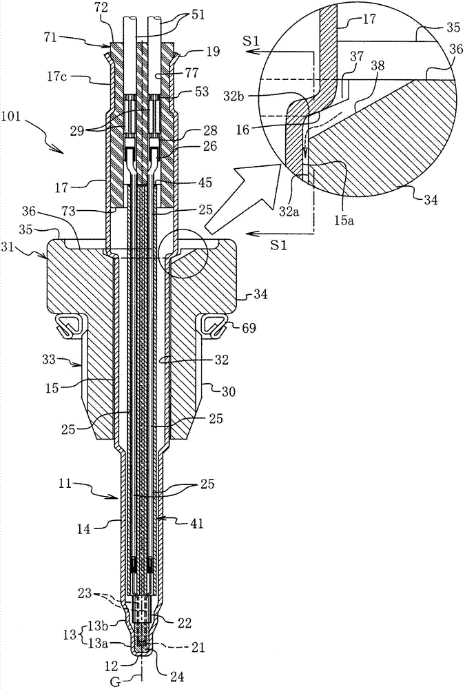
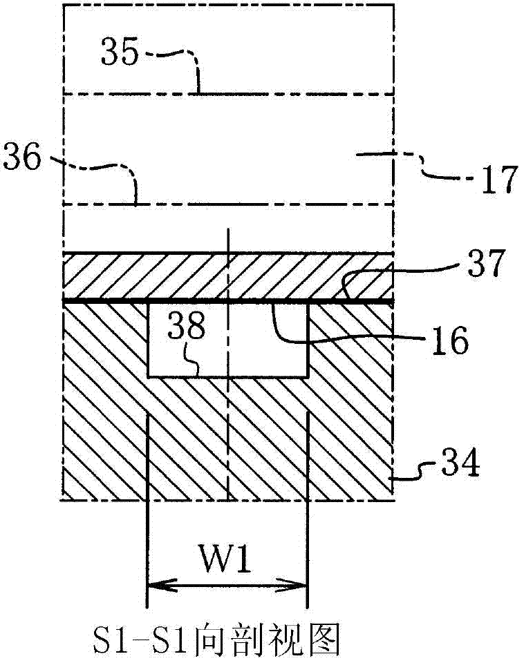
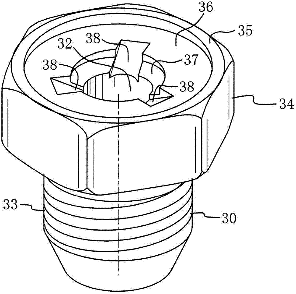
[0064] Regarding the embodiment (first embodiment) of the sensor embodying the present invention, based on Figure 1 to Figure 7 Describe in detail. figure 1 , reference numeral 101 is a sensor, which consists of a front end ( figure 1 The lower end) 12 of the tube 11 is made of metal (for example, made of SUS) closed, and the sensor element 21 arranged inside the front end 12 of the tube 11 or near the front end and the like. The tube 11 on which the element 21 is placed is inserted into a tube insertion hole 32 formed so as to surround the tube 11 at the center (inner side) of a ring-shaped attachment metal fitting 31 made of SUS, for example. The annular (cylindrical) circular hole is welded between the outer peripheral surface of the tube 11 and the inner peripheral surface 32 a of the tube insertion hole 32 with, for example, brazing (not shown). In addition, the ring-shaped mounting metal fitting 31 is formed such that an annular portion (cylindrical portion) 33 havi...


PUM


Abstract

A sensor including a tube having a small-diameter portion loosely inserted into a tube insertion hole(32) of an annular mounting fixture and a large-diameter portion having a diameter larger than an inside diameter of the tube insertion hole. A flow path(38) is formed, so that when the large-diameter portion(17) of the tube(11) is locked on the rear end(32b) of the tube insertion hole, a rear end of a gap, defined between an inner circumferential surface of the tube insertion hole and an outer circumferential surface of the small-diameter portion(15) of the tube, remains open. Further, the inner circumferential surface of the tube insertion hole and the outer circumferential surface of the small-diameter tubular portion of the tube are brazed together with a brazing filler which flows into the gap.

Description

technical field [0001] The present invention relates to a sensor for measuring the temperature of fluids such as engine exhaust, and more specifically, the present invention relates to a sensor suitable for the following working conditions: sensing elements such as thermistors of the sensor (hereinafter also referred to as sensors) Sensing element or element for short) is arranged at the front end or near the front end of a tube with a closed end (a tube or cover with one end open), by exposing the part of the tube near the front end to the heat of the exhaust gas The middle method is installed on the installation target site such as the exhaust manifold (exhaust pipe), and the heat is transferred to the internal sensor element to measure (detect) the temperature of the exhaust gas. Background technique [0002] Conventionally, various configurations have been proposed as such sensors (temperature sensors) (for example, refer to Patent Document 1). In the sensor disclosed i...

Claims


Application Information

Patent Timeline
Patent Type & Authority Applications(China)
IPC IPC(8): F01N13/18F01N11/00
CPCG01K2205/04G01K1/14F01N13/008B23K1/0008B23K1/20B23K2101/06B23K2101/36
Inventor 茂刈贤史伊藤政伦石川聪
Owner NGK SPARK PLUG CO LTD
Learn More