Fiber bragg grating based composite material thermal expansion coefficient measuring device and measuring method

A technology of thermal expansion coefficient and fiber grating, applied in the field of measurement, can solve the problems that fiber grating cannot be reused, cannot meet higher precision requirements, and low resolution cannot meet requirements, etc., achieve high precision requirements, improve measurement sensitivity, and work reliably good sex effect

Active Publication Date: 2012-11-21
NANJING UNIV OF AERONAUTICS & ASTRONAUTICS
View PDF5 Cites 20 Cited by
  • Summary
  • Abstract
  • Description
  • Claims
  • Application Information

AI Technical Summary

Problems solved by technology

The optical lever method cannot meet the requirements because of its low resolution; the moiré method is destructive to the material and affects the performance of the material; the laser scanning micrometry method and the electronic speckle method put forward higher environmental and equipment requirements for measurement , susceptible to interference and error; the fiber grating method is to fix the grating on the surface of the material or embed it inside the material, heat it together with the material, directly measure its thermal expansion, and then obtain the measurement result through theoretical calculation, but after the measurement, the optical fiber The grating cannot be reused, and it must be recalibrated when it is measured again; the absolute measurement method only basically guarantees the accuracy of the measurement, and cannot meet the higher accuracy requirements

Method used


Image

  • Fiber bragg grating based composite material thermal expansion coefficient measuring device and measuring method
  • Fiber bragg grating based composite material thermal expansion coefficient measuring device and measuring method
  • Fiber bragg grating based composite material thermal expansion coefficient measuring device and measuring method

Examples


Embodiment Construction

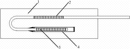
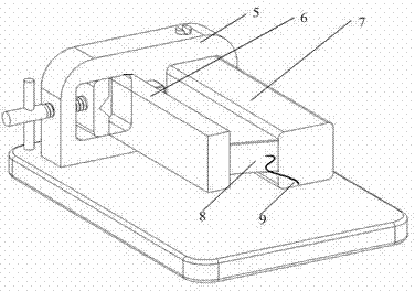
[0021] The measurement means and method are realized through the following technical solutions: a fiber grating-based thermal expansion coefficient test experimental device, including a standard sample block with a known thermal expansion coefficient, whose CTE is greater than the estimated value of the composite material; fixed standard sample block And the fixture of the composite material block to be tested has the function of adjusting the clamping position; the fiber grating sensor of the strain-intensified package, the fiber grating demodulator, and the temperature control box.

[0022] The composite material block to be tested and the standard sample block are fixed on the fixture in parallel, the distance between the composite material and the standard sample block is fixed, and the length of the free end of the test piece is greater than that of the composite material. One end of the encapsulated grating sensor is fixed on the free end of the standard sample block, and...


PUM


Abstract

Belonging to the field of measurement technologies, the invention relates to a fiber bragg grating based composite material thermal expansion coefficient measuring device and a measuring method. The device comprises a fixture (5), a standard test block (7), a composite material block to be measured (6) and a fiber bragg grating sensor (8). Specifically, one end of the fiber bragg grating sensor (8) is fixed with a free end of the standard test block (7), and the other end is fixed with the free end of the composite material block to be measured (6). The fiber bragg grating sensor, the composite material block to be measured, and the standard test block are placed in a temperature control box. The composite material block to be measured and the standard test block can expand after being heated, and their different change degrees can generate a pull effect on the fiber bragg grating sensor and cause changes of a grating central wavelength. By combining the fiber bragg grating strain sensitivity and a relative measurement method, accurate measurement of the thermal expansion coefficient in different length sections of a composite material can be realized.

Description

technical field [0001] The invention relates to the technical field of measurement, in particular to the measurement of the coefficient of thermal expansion of composite materials. Background technique [0002] Materials in nature will expand or contract due to temperature changes, and the coefficient of thermal expansion (CTE) is often used to describe the degree of change. It is generally considered that CTE is the ratio of the change in the length of the object with the change of unit temperature to the original length of the object at the reference temperature. [0003] With its unique advantages, composite materials are widely used in various engineering fields; thermal expansion coefficient is used to indicate the inherent property of the material itself when heated and deformed, and has important reference value in engineering design, precision instrument manufacturing, material welding and processing; as a composite material Its measurement result is an important pa...

Claims


Application Information

Patent Timeline
Patent Type & Authority Applications(China)
IPC IPC(8): G01N25/16
CPCG01N25/16
Inventor 曾捷周雅斌穆昊孙晓明张倩昀
Owner NANJING UNIV OF AERONAUTICS & ASTRONAUTICS
Why Eureka
Try Eureka