Time-division frequency-division multiplexing rotor-type micro-gyroscope detection device

A technology of frequency division multiplexing and detection device, which is applied in the field of micro-gyroscope detection to achieve the effect of eliminating cross-sensitivity

Active Publication Date: 2016-08-03
HARBIN INST OF TECH
View PDF1 Cites 0 Cited by
  • Summary
  • Abstract
  • Description
  • Claims
  • Application Information

AI Technical Summary

Problems solved by technology

[0003] The purpose of the present invention is to solve the problems existing in the two existing differential capacitance detection methods, and to provide a rotor-type micro-gyroscope detection device with time-division frequency-division multiplexing

Method used


Image

  • Time-division frequency-division multiplexing rotor-type micro-gyroscope detection device
  • Time-division frequency-division multiplexing rotor-type micro-gyroscope detection device

Examples


specific Embodiment approach 1

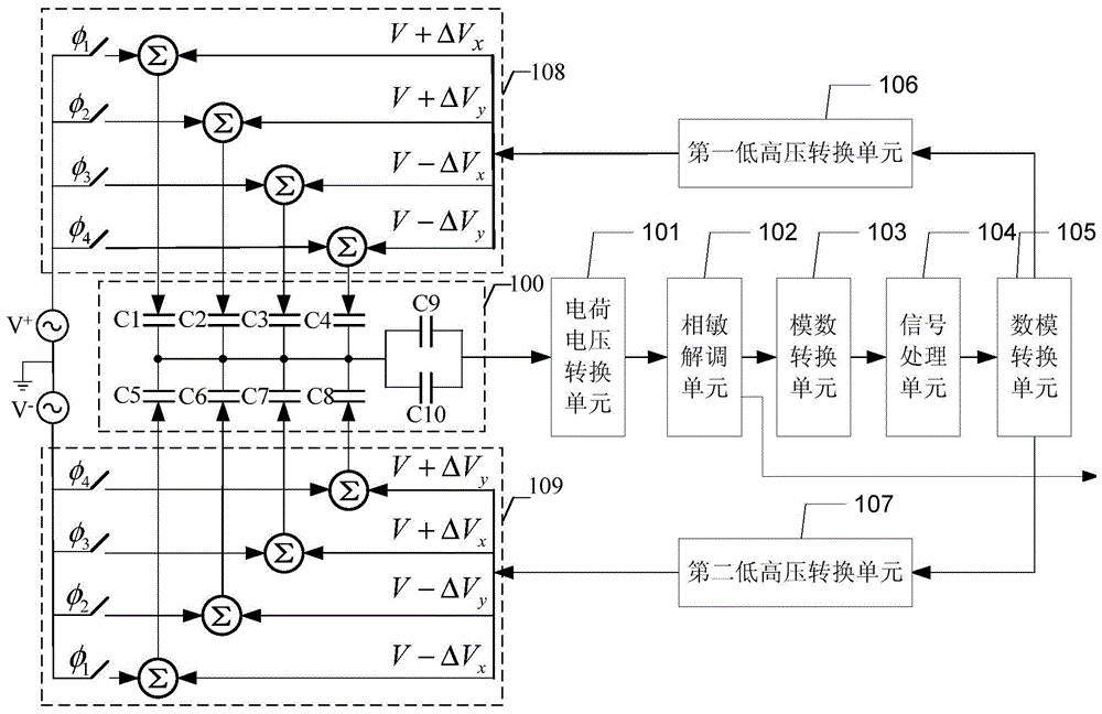
[0019] Specific implementation mode one: the following combination figure 1 Describe this embodiment mode, the time-division-frequency-division-multiplexing rotor-type micro-gyroscope detection device described in this embodiment mode, which includes a rotor-type micro-gyroscope sensitive unit 100, a charge-voltage conversion unit 101, a phase-sensitive demodulation unit 102, and an analog-to-digital conversion unit 103 , a signal processing unit 104, a digital-to-analog conversion unit 105, a first low and high voltage conversion unit 106, a second low and high voltage conversion unit 107, a first time division frequency division multiplexing unit 108 and a second time division frequency division multiplexing unit 109;

[0020] The carrier excitation signal V of the first time division frequency division multiplexing unit 108 + Multiplexed with the feedback control signal and loaded to the first group of multiplexed signal input terminals of the rotor-type micro-gyroscope sen...

specific Embodiment approach 2

[0031] Embodiment 2: This embodiment will further explain Embodiment 1. The rotor-type micro-gyroscope sensitive unit 100 includes four pairs of differential capacitors and a pair of pickup capacitors. The four pairs of differential capacitors are C1, C5; C2, C6; C3, C7 ; With C4, C8; the pair of pickup capacitors are C9, C10; pickup capacitors C9 and C10 are connected in parallel;

[0032] The multiplexing signal loaded by the differential capacitors C1, C2, C3 and C4 is the carrier excitation signal V + and feedback control signal; the multiplexing signal loaded by differential capacitors C5, C6, C7 and C8 is the carrier excitation signal V - and feedback control signals;

[0033] The differential capacitor C1 multiplexes and loads the carrier excitation signal V + and feedback control signal V+ΔV x ;

[0034] The differential capacitor C2 multiplexes and loads the carrier excitation signal V + and feedback control signal V+ΔV y ;

[0035] The differential capacitor C...

specific Embodiment approach 3

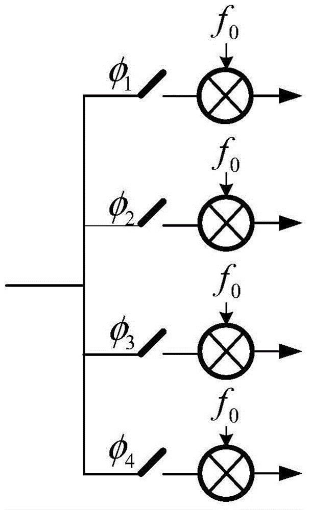
[0043]Specific embodiment three: this embodiment will further explain embodiment one, the first time division frequency division multiplexing unit 108 and the second time division frequency division multiplexing unit 109 have the same structure, both are composed of a switch network and a summation unit, so The above switch network is a group of time switches φ 1 , φ 2 , φ 3 , φ 4 ; Controlled by a time-sharing switch, and load the multiplexing signal through the summation unit;

[0044] Time division switch φ in the first time division frequency division multiplexing unit 108 1 , φ 2 , φ 3 , φ 4 Control the loading of differential capacitors C1, C2, C3 and C4 respectively;

[0045] Time division switch φ in the second time division frequency division multiplexing unit 109 1 , φ 2 , φ 3 , φ 4 Control the loading of differential capacitors C5, C6, C7 and C8 respectively.


PUM


Abstract

The invention discloses a time division and frequency division multiplexing rotor type micro-gyro detector which belongs to the field of MEMS (Micro Electro Mechanical Systems) components and aims to solve the problems of two existing differential capacity detection methods. The time division and frequency division multiplexing rotor type micro-gyro detector comprises a rotor type micro-gyro sensing unit, a charge voltage conversion unit, a phase-sensitive demodulating unit, an analog-digital conversion unit, a signal processing unit, a digital-analog conversion unit, a first low voltage and high voltage conversion unit, a second low voltage and high voltage conversion unit and two time division and frequency division multiplexing units, wherein carrier wave excitation signals V+ and V- of the two time division and frequency division multiplexing units and a feedback control signal are multiplexed and loaded to the rotor type micro-gyro sensing unit; an equivalent gyro signal output end of the rotor type micro-gyro sensing unit is connected with the input end of the phase-sensitive demodulating unit; a demodulation signal output end of the phase-sensitive demodulating unit is used for outputting a detection signal and connected with an analog signal input end of the analog-digital conversion unit; subsequently, analog to digital conversion, signal processing, digital to analog conversion and low voltage to high voltage transformation are performed, and then results are fed back to the two time division and frequency division multiplexing units.

Description

technical field [0001] The invention relates to a micro-gyroscope detection technology and belongs to the field of MEMS devices. Background technique [0002] For the detection circuit of high-precision micro-sensors, especially the rotor-type micro-gyro sensor, the angular velocity signal detection is realized based on the rotor deflection angle method, and the displacement signal is picked up by using the differential capacitance detection method. Compared with other detection methods, this method has high detection accuracy (<10 -14 meters), high linearity (<10 -4 ), non-contact measurement and other technical advantages. At present, there are mainly two differential capacitance detection methods. The first one is to use the middle electrode excitation (single frequency) method to detect multiple sets of capacitance changes at the same time. However, due to the high resistance characteristics of the charge amplifier, it is easy to form interference with the same f...

Claims


Application Information

Patent Timeline
Patent Type & Authority Patents(China)
IPC IPC(8): G01C19/08G01C19/02
CPCG01C19/02G01C19/08
Inventor 刘晓为尹亮陈伟平任明远张海峰李海付强
Owner HARBIN INST OF TECH
Why Eureka
Try Eureka