Eureka AIR delivers breakthrough ideas for toughest innovation challenges, trusted by R&D personnel around the world.

Nuclear energy monitoring optical cable

An optical cable and nuclear energy technology, applied in the field of optics, can solve the problems of causing disasters, causing danger, whether fission energy can be used for power generation, etc., to achieve the effect of reducing external radiation and solving radiation resistance

Inactive Publication Date: 2012-11-21
东捷光电科技(苏州)有限公司
View PDF5 Cites 3 Cited by
  • Summary
  • Abstract
  • Description
  • Claims
  • Application Information

AI Technical Summary

Problems solved by technology

[0003] But, have following shortcoming simultaneously: 1. Nuclear reaction must be controlled by people through certain device, and the uncontrolled fission energy not only can't be used for generating electricity, also can cause disaster; The hazards are great, and we must try to avoid their harm to the staff of the nuclear power plant and nearby residents; 3. There are a large amount of radioactive substances in the reactor of the nuclear power plant. If they are released into the external environment in an accident, they will cause harm to the ecology and the people.
[0004] Because nuclear power generates a lot of heat, but the power generation efficiency is very low, only a small part is used for power generation, and most of it is discharged into the surrounding environment
Failure to dissipate heat in time can be dangerous, so the temperature of a nuclear power plant must be monitored
At the same time, neutrons, γ-rays and thermal radiation, especially γ-ray radiation, which are very harmful to the human body, will be produced in the process of nuclear power generation. The general monitoring system and monitoring products cannot meet the requirements of long-term stable operation.

Method used


Image

  • Nuclear energy monitoring optical cable

Examples


Embodiment Construction

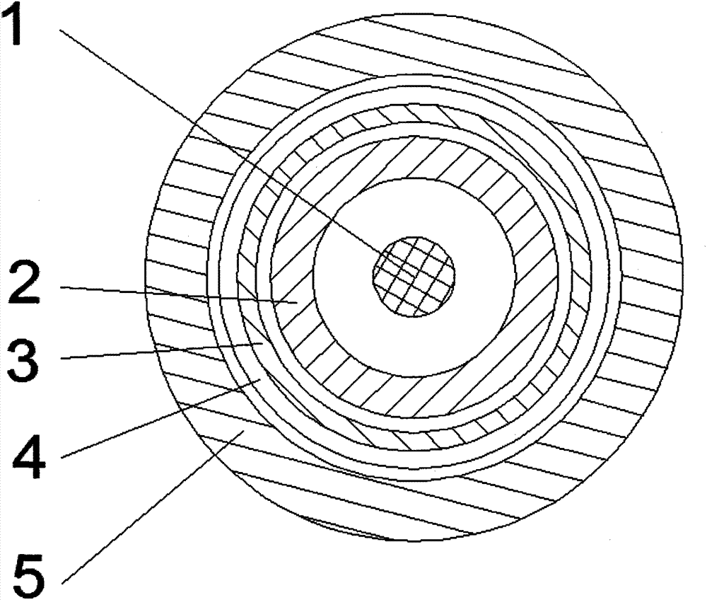
[0018] as attached figure 1 The shown nuclear energy monitoring optical cable according to the present invention includes a monitoring optical fiber 1 for temperature sensing and signal transmission, a radiation-proof metal tube 2, an aramid fiber 3, a metal shielding net 4, and a radiation-proof optical cable outer sheath. Cover 5; the radiation-proof metal tube 2 wraps the monitoring optical fiber 1; the aramid fiber 3 wraps the radiation-proof metal tube 2; the metal shielding net 4 wraps the aramid fiber 3; the radiation-proof optical cable outer sheath 5 wraps Metal shielding net 4; described monitoring optical fiber 1 is 1 core to 166 cores; described anti-radiation metal pipe 2 is metal spiral pipe or metal seamless pipe or metal nodular pipe; described anti-radiation metal pipe 2 is made of Made of stainless steel wire or special steel wire; the metal spiral tube is single-layer or double-layer twisted, and the double-layer twist is double-layer twisted in the same dir...


PUM


Abstract

The invention discloses a nuclear energy monitoring optical cable which comprises monitoring optical fibers, a radiation prevention metal tube, aramid fibers, a metal shielding net and a radiation prevention optical cable outer sheath, wherein the monitoring optical fibers are used for temperature sensation and signal transmission; the radiation prevention optical cable outer sheath is used for wrapping the monitoring optical fiber; the radiation prevention metal tube is wrapped by the aramid fibers; the aramid fibers are wrapped by the metal shielding net; and the metal shielding net is wrapped by the radiation prevention optical cable outer sheath. With the adoption of the invention, firstly, the problem of temperature monitoring is solved, and the function that the temperature monitoring can be carried out on a nuclear power station is accomplished; and secondly, the problem of radiation prevention of a monitoring system is solved; as the nuclear energy monitoring optical cable provided by the invention is provided with the radiation prevention optical cable outer sheath, the metal shielding net and the radiation prevention metal tube, the external radiation can be reduced or even eliminated effectively.

Description

technical field [0001] The invention relates to a monitoring optical cable, in particular to an optical cable detection main body with optical fiber as the main body, which is used in a temperature monitoring system for nuclear power generation, and belongs to the field of optical technology. Background technique [0002] Nuclear power generation uses the heat generated by nuclear fission chain reaction of uranium fuel to heat water to high temperature and high pressure. The heat released by the nuclear reaction is much higher than the energy released by burning fossil fuels. The difference is about a million times. Compared with all the required fuel The volume is considerably less than thermal power plants. Compared with traditional thermal power generation, it has the following advantages: 1. Nuclear power generation does not emit huge amounts of pollutants into the atmosphere like fossil fuel power generation, so nuclear power generation will not cause air pollution; 2. ...

Claims


Application Information

Patent Timeline
IPC IPC(8): G02B6/44G21C17/00G21F1/12
CPCY02E30/30
Inventor 吕政鸿
Owner 东捷光电科技(苏州)有限公司
Why Eureka
Eureka Blog
Learn More