Wireless illumination control system and remote controller and system manager thereof

A control system and wireless lighting technology, applied in lighting devices, signal transmission systems, energy-saving control technology, etc., can solve problems such as fast energy consumption, limited number of LED lights, slow start or restart of remote control, etc., to reduce energy consumption, Easy setup, startup and restart for fast results

Inactive Publication Date: 2012-11-21
MASS TECH (HK) LTD
View PDF18 Cites 71 Cited by
  • Summary
  • Abstract
  • Description
  • Claims
  • Application Information

AI Technical Summary

Problems solved by technology

[0006] In the above-mentioned prior art, since dry batteries are generally used as the power supply of the remote controller, the transceiver in the remote controller is used not only to transmit dimming signals, but also to continuously communicate with the driving devices of each lamp, so its energy consumption is very high. Fast; and the control range of the remote control is not large, generally only within a radius of about 5-10 meters; at the same time, the start or restart of the remote control is also very slow
In addition, the LED lamps in the prior art are generally controlled to be turned on simultaneously with the same brightness, and when the brightness of the LED lamps is different, the number of LED lamps that can be controlled by the remote controller is also very limited, for example, only a few groups LED lights with different brightness

Method used


Image

  • Wireless illumination control system and remote controller and system manager thereof
  • Wireless illumination control system and remote controller and system manager thereof
  • Wireless illumination control system and remote controller and system manager thereof

Examples


Embodiment Construction

[0049] Hereinafter, the present invention will be described in further detail through the structure and operation of the preferred embodiment with reference to the accompanying drawings. The embodiments described below are illustrative only and should not be construed as limiting the scope of the present invention.

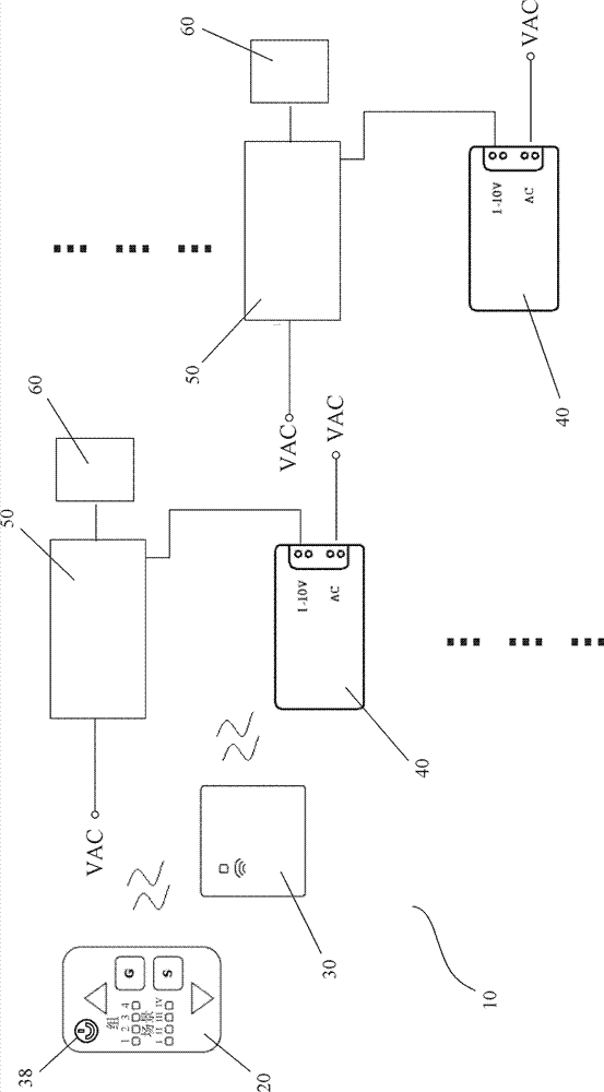
[0050] figure 1 is a schematic diagram of an embodiment of the wireless lighting control system of the present invention, wherein the structure of the wireless lighting control system of the present invention is represented in the form of a block diagram. Such as figure 1 As shown, the wireless lighting control system 10 of the present invention includes a remote controller 20 , a system manager 30 , a plurality of dimmers 40 , a plurality of drivers 50 , and a plurality of lamps 60 . figure 1 "..." in indicates that the wireless lighting control system may include multiple sets including dimmers 40 , drivers 50 and lamps 60 . When the lamp 60 is an LED lamp, t...


PUM


Abstract

The invention discloses a wireless illumination control system which comprises a remote controller, a system manager, a plurality of dimmers, a plurality of drivers and a plurality of lamps, wherein the remote controller is in coupling connection with the system manager; the system manager is in coupling connection with each dimmer; commands are sent to the system manager by the remote controller; the system manager is used for converting the commands into control signals and sending the control signals to the corresponding dimmer; the dimmers are used for converting the control signals into dimming control signals and transmitting the dimming control signals onto the corresponding drivers; each driver is used for ensuring the corresponding lamp to emit light on the corresponding brightness level according to the corresponding dimming control signal; a plurality of lamps can be divided into a plurality of groups; a plurality of groups of lamps correspond to the setting of G keys on the remote controller; and the setting of one group of G keys can be named one scene S. According to the invention, 50 or more dimmers can be conveniently controlled, a range of 50 meters can be covered and the energy consumption of the remote controller is obviously reduced.

Description

technical field [0001] The present invention relates to a wireless lighting control system, suitable for a lighting system with a light source driver, wherein the driver has a 1-10V dimming function; preferably, the present invention relates to a system for controlling a lighting system containing a plurality of LED (Light Emitting Diode) lamps Wireless control system. Background technique [0002] LED lamps have the advantages of environmental protection, energy saving, and adjustable brightness, and are more and more widely used in lighting, screen display and other fields. However, the brightness of a single LED lamp is usually not large enough. Therefore, when LED lamps are used for large lighting occasions, multiple LED lamps need to be used. They can be arranged together or separately in different positions in the space to make the lighting more uniform. In addition, when there are a large number of LED lights, for example, in indoor, outdoor, on-site lighting, stage ...

Claims


Application Information

Patent Timeline
Patent Type & Authority Applications(China)
IPC IPC(8): H05B37/02G08C17/02
CPCY02B20/46Y02B20/40
Inventor 胡安华
Owner MASS TECH (HK) LTD
Why Eureka
Try Eureka