Bending type forming method of corner cut waveguide bend

A bending waveguide and angle-cutting technology, which is applied in the field of angle-cutting bending waveguide bending, can solve the problems of many splicing surfaces, high probability of welding defects, and high welding difficulty, so as to reduce the size error of the inner cavity and reduce the probability of misalignment defects , Improve the effect of cavity forming precision

Active Publication Date: 2012-11-28
XIAN INSTITUE OF SPACE RADIO TECH
View PDF4 Cites 11 Cited by
  • Summary
  • Abstract
  • Description
  • Claims
  • Application Information

AI Technical Summary

Problems solved by technology

The disadvantage is that the waveguide part is tailor-welded in three pieces, and there are many splicing surfaces. The forming accuracy of the inner cavity is affected by factors such as the dimensional tolerance of the two waveguides, the assembly positioning accuracy, and the welding accuracy. After welding, the dimensional stability of the inner cavity is low, and it is easy to appear Quality

Method used


Image

  • Bending type forming method of corner cut waveguide bend
  • Bending type forming method of corner cut waveguide bend
  • Bending type forming method of corner cut waveguide bend

Examples


Embodiment

[0038] Aluminum waveguide anti-rust aluminum alloy LF21 chamfered bending waveguide bending method, the specific steps are:

[0039] 1) Processing waveguide:

[0040] The material is aluminum alloy standard model BJ40 rectangular waveguide, the inner cavity width is 58.17mm, the height is 29.08mm, and the wall thickness is 1.5mm.

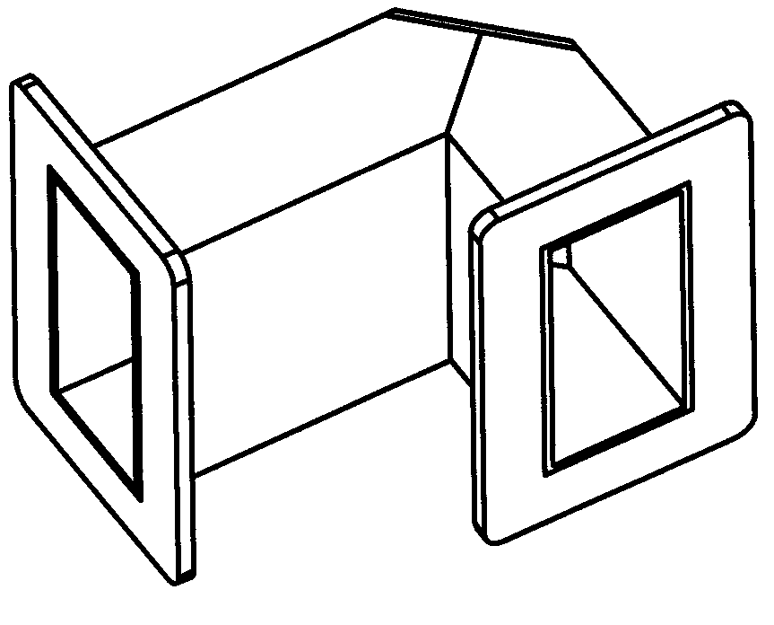
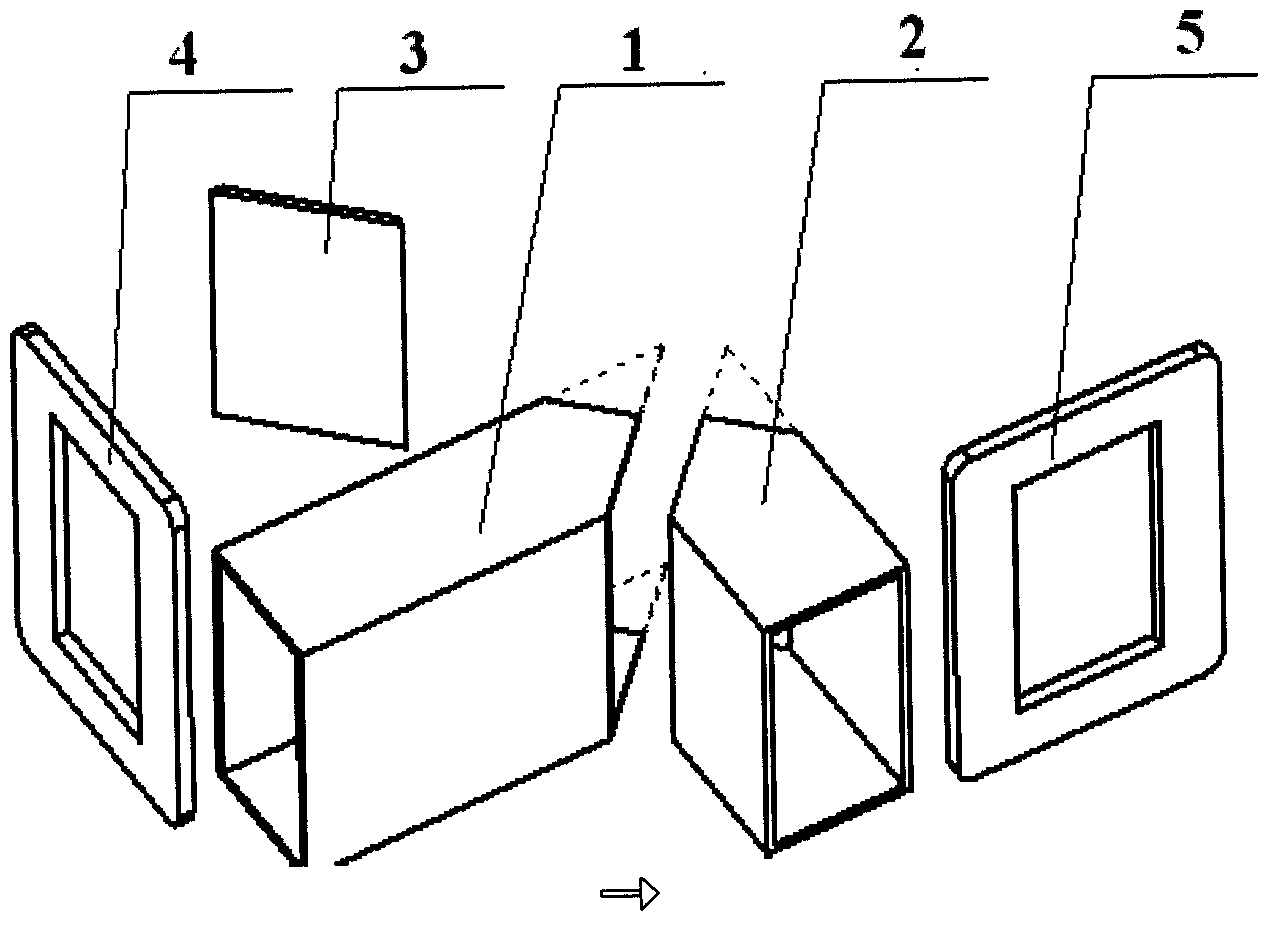
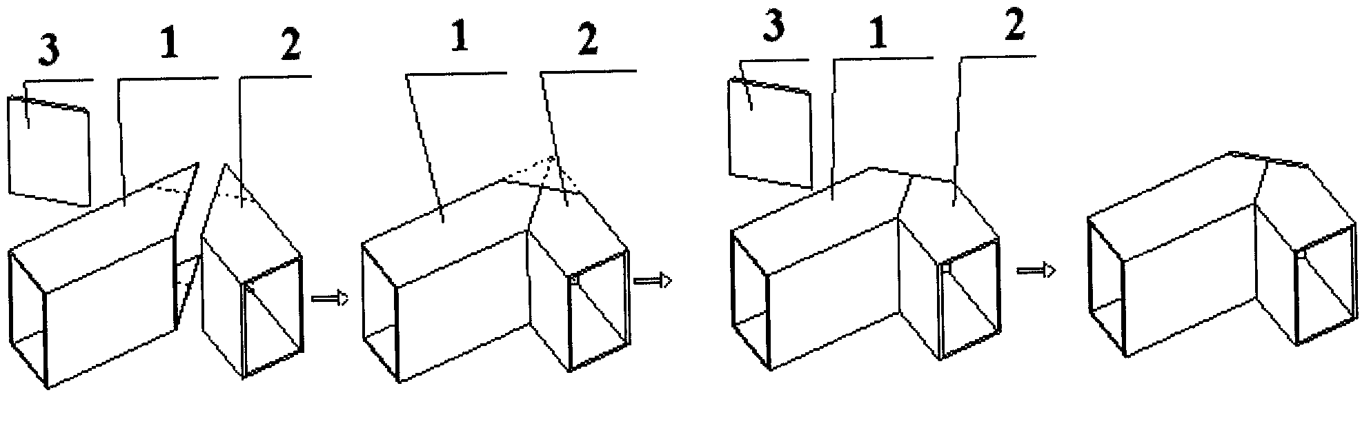
[0041] Such as Figure 4 As shown, the triangular bending groove A10 and the triangular bending groove B11 are processed on the rear surface of the aluminum waveguide, and the waveguide is divided into three parts in the length direction. Tube B8; B0=50.51mm is the length of the inner surface of the folding area 9, B is the distance between the triangular bending groove A10 and the triangular bending groove B11, after considering the bending stretch and weld gap, take B=50.91mm .

[0042] Such as Figure 5 As shown, bending gaps are processed on the front surface, upper surface and lower surface of the waveguide, an inverted trapezoid abdc is cu...


PUM

PropertyMeasurementUnit
Heightaaaaaaaaaa
Wall thicknessaaaaaaaaaa

Abstract

The invention relates to a bending type forming method of a corner cut waveguide bend, which belongs to the technical field of waveguide forming. Two triangular bending grooves are formed in the rear surface of a waveguide tube and divide the waveguide tube into three parts in the length direction, wherein the center part of the waveguide tube is a bending area. Bending gaps are processed in the front surface, the upper surface and the lower surface of the waveguide tube; the rectangular waveguide tube is folded forwards along the two triangular bending grooves; and flanges are welded at the two ends of the formed waveguide tube to obtain the corner cut waveguide bend. According to the bending type forming method, the same waveguide tube is adopted for forming, so that the dimension error of an inner cavity assembled by different waveguide tube blanks is reduced, and the probability of dislocation deficiency of the splicing surface of the inner cavity is reduced; a bending type self-positioning structure is adopted to control the inner cavity forming, so that the effects of assembling and welding on the precision of the dimension, shape and position of the inner cavity are reduced, and the forming precision of the inner cavity is improved; the waveguide tube part is subjected to once weld forming, so that welded joints of the inner cavity are decreased; the difficulty in welding is reduced; the stability of the welding quality is improved; and the welding efficiency is improved.

Description

technical field [0001] The invention relates to a bending forming method of a chamfered waveguide, which belongs to the technical field of waveguide forming. Background technique [0002] Generally, angle-cutting bend waveguide is used to realize microwave channel connection. The common bend waveguide structure design and process methods include integral forming, waveguide plus flange welding forming process technology. Due to the low overall processing efficiency and high cost, the waveguide and flange welding forming structure is preferred under the condition that the design accuracy can be satisfied. [0003] In the prior art, the chamfered bend waveguide welding structure such as figure 1 As shown, its composition diagram is shown in figure 2 As shown, the angle-cut bend waveguide is composed of waveguide 1, waveguide 2, blocking plate 3, flange 4 and flange 5, and the waveguide uses waveguide 1, waveguide 2 and blocking plate 3 through secondary welding shaped like ...

Claims


Application Information

Patent Timeline
IPC IPC(8): B23P15/00
Inventor 范铁军王艳枝韩廷华戴建京李静张文科刘云天周虹李毅吕俊林张军娟林琳
Owner XIAN INSTITUE OF SPACE RADIO TECH
Why Eureka
Try Eureka