
Automatic control system and method for underground annulus pressure of deep water surface layer drilling

An automatic control system and annulus pressure technology, which are applied in the automatic control system of drilling, drilling equipment, earth-moving drilling, etc., can solve problems such as difficulty in balancing formation pressure, prone to kick or lost circulation, and errors.

Active Publication Date: 2015-01-14
CHINA NAT OFFSHORE OIL CORP +1
View PDF9 Cites 1 Cited by
  • Summary
  • Abstract
  • Description
  • Claims
  • Application Information

AI Technical Summary

Problems solved by technology

Only by manually setting the opening of the regulating valve to control the mixing ratio of heavy slurry and seawater, there will be a large error between the control result and the actual downhole demand. The liquid column pressure generated by the mud at the bottom of the well is difficult to balance the formation pressure, and well kick or Lost circulation can lead to drilling accidents. Therefore, it is necessary to develop a control system that can automatically adjust the mixing ratio of heavy mud and seawater according to the formation pressure profile, and configure the drilling mud with the required density and flow rate to enter the downhole, so as to realize the automatic adjustment of downhole annular pressure. System and Control Method

Method used


Image

  • Automatic control system and method for underground annulus pressure of deep water surface layer drilling
  • Automatic control system and method for underground annulus pressure of deep water surface layer drilling
  • Automatic control system and method for underground annulus pressure of deep water surface layer drilling

Examples


Embodiment Construction

[0067] The present invention will be described in detail below in conjunction with the accompanying drawings and embodiments.

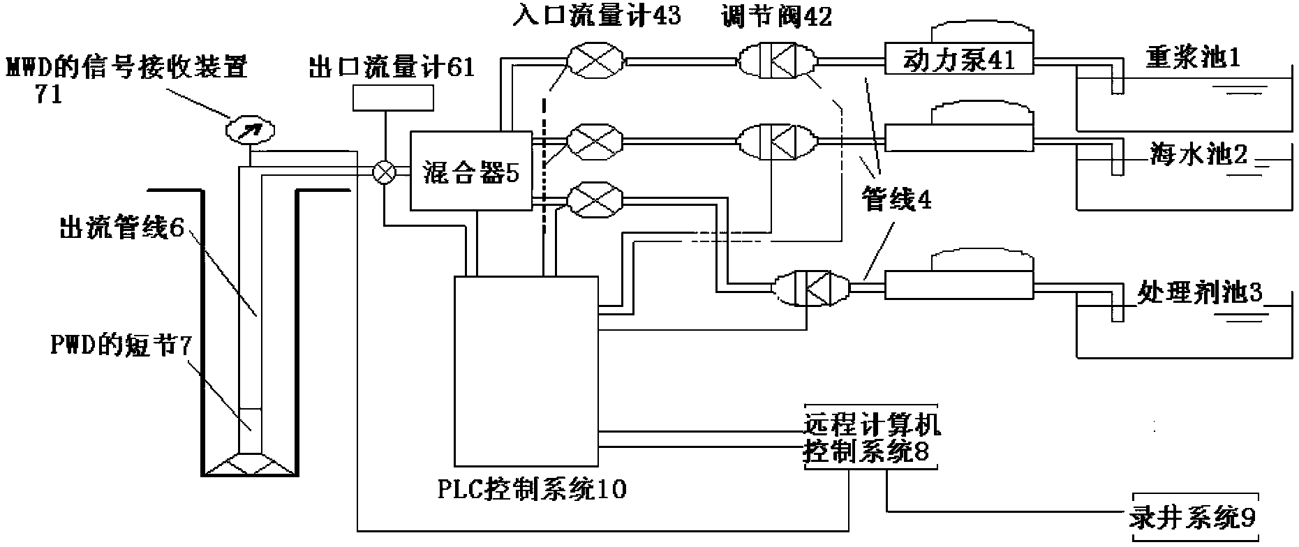
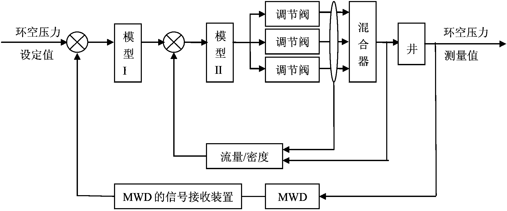
[0068] Such as figure 1 , figure 2 As shown, the system of the present invention includes a heavy slurry tank 1, a seawater tank 2 and a treatment agent tank 3 arranged on the sea surface, and a pipeline 4 is respectively arranged in the heavy slurry tank 1, seawater tank 2 and treatment agent tank 3, and each pipeline 4 The end of the mixer is connected to the input end of a mixer 5, and the output end of the mixer 5 is connected to the short joint 7 of the PWD (Pressure While Drilling, pressure measurement system while drilling) under the seabed through an outlet pipeline 6. Each pipeline 4 is provided with a power pump 41 , a regulating valve 42 and an inlet flowmeter 43 , and the outlet pipeline 6 is provided with an outlet flowmeter 61 . MWD (Measure While Drilling, measurement while drilling) (not shown in the figure) is set on the PWD, and t...


PUM


Abstract

The invention relates to an automatic control system and method for underground annulus pressure of deep water surface layer drilling. The system comprises three pipelines which are respectively arranged in a heavy slurry pond, a seawater pond and a treating agent pond, wherein each pipeline is connected with the input end of a mixer, the output end of the mixer is connected with an outflow pipeline, and the outflow pipeline is connected with a pup joint of a seabed underground PWD. Each pipeline is internally provided with a power pump, a regulating valve and an inlet flow meter, and the outflow pipeline is internally provided with an outlet flow meter. The underground PWD is connected with an MWD, a signal receiving device of the MWD is in communication connection with a remote computer control system, the remote computer control system is connected with a logging system and a PLC (Programmable Logic Controller) control system through a data bus, and the PLC control system is connected with the regulating valve, the inlet flow meter, the mixer and the outlet flow meter through data. According to the invention, a secondary microcomputer control system is created through the remote computer control system and the PLC control system, so that the mixing proportion of heavy slurry and seawater is automatically regulated, and drilling slurry with required density and flow is input to the underground to carry out underground pressure balance regulation to further realize safe drilling.

Description

technical field [0001] The invention relates to an automatic control system and control method for downhole annular pressure, in particular to an automatic control system and control method for downhole annular pressure in deepwater surface drilling for ocean riser-free drilling. Background technique [0002] During the drilling process, using the hydrostatic column pressure generated by the mud at the bottom of the well to balance the formation pressure is a conventional technical means to prevent well kick or lost circulation and ensure safe drilling operations. When drilling in the deep water surface of the ocean, formation instability, shallow gas and shallow water flow, and the low-temperature and high-pressure environment of the seabed cause rheological changes in drilling fluid, resulting in the formation of gas hydrates, and the gap between formation pressure and formation fracture pressure The window is narrow and many other problems. Because there are no wellheads...

Claims


Application Information

Patent Timeline
Patent Type & Authority Patents(China)
IPC IPC(8): E21B44/00
Inventor 殷志明李嗣贵雷宗明胡文金李迅科朱荣东孔松涛汤毅田波罗洪斌艾传志田峥
Owner CHINA NAT OFFSHORE OIL CORP
Learn More