Binary stripe stack based sinusoidal grating generation method

A sinusoidal grating and binary technology, applied in the direction of using optical devices, measuring devices, instruments, etc., can solve the problems of increasing the number of projected pictures, a large amount of time, and a large amount of calculation, and achieve the effect of avoiding errors

Inactive Publication Date: 2012-11-28
NORTHWESTERN POLYTECHNICAL UNIV
View PDF4 Cites 11 Cited by
  • Summary
  • Abstract
  • Description
  • Claims
  • Application Information

AI Technical Summary

Problems solved by technology

These methods can greatly improve the measurement accuracy, but there are also some defects: the spline fitting method needs multiple iterations in the phase calculation, and the amount of cal

Method used


Image

  • Binary stripe stack based sinusoidal grating generation method
  • Binary stripe stack based sinusoidal grating generation method
  • Binary stripe stack based sinusoidal grating generation method

Examples


Embodiment Construction

[0028] Describe the present invention below in conjunction with specific embodiment:

[0029] In this embodiment, the sinusoidal grating generation method based on binary fringe superposition comprises the following steps:

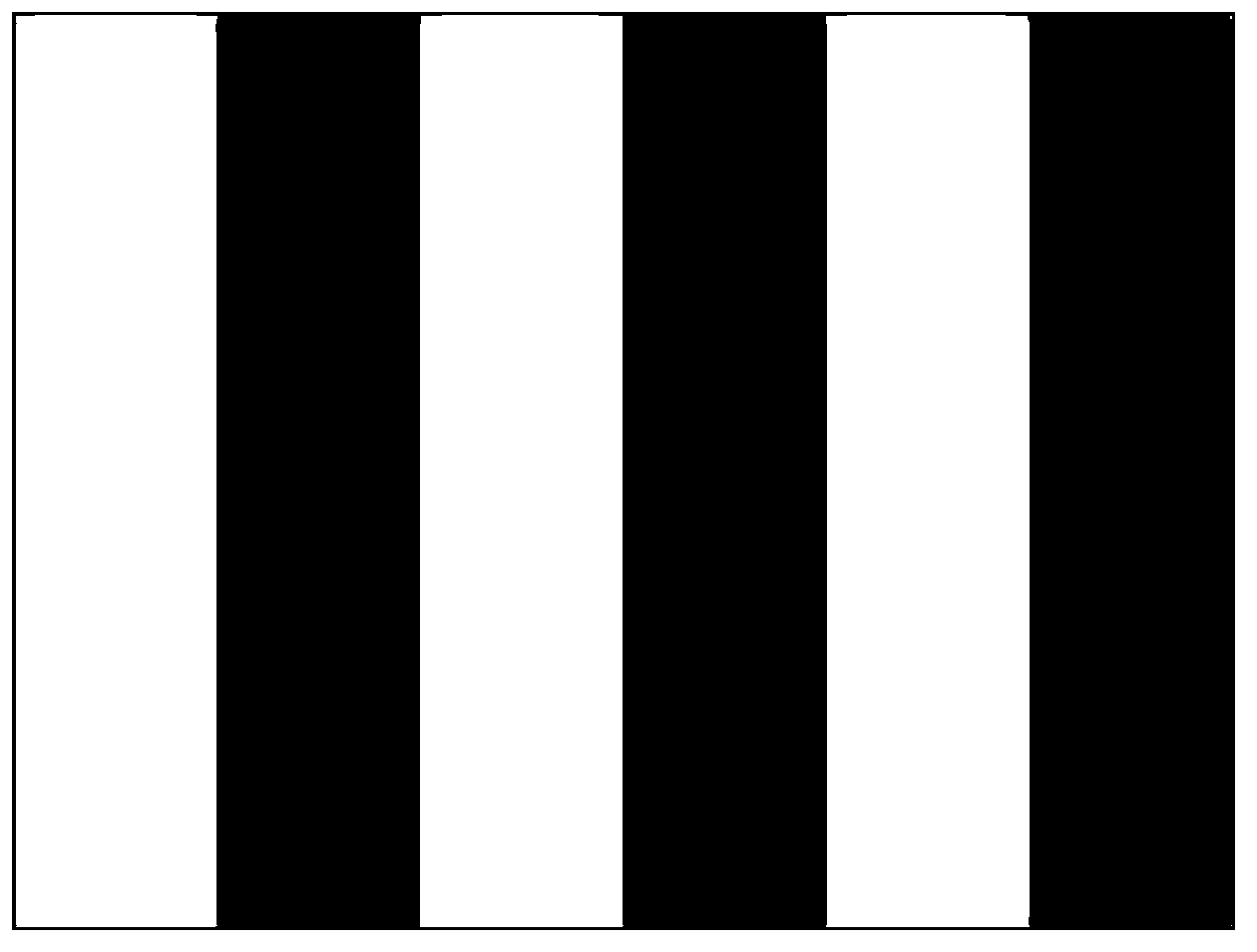
[0030] Step 1: Generate a sinusoidal grating pattern A with at least two periods; as attached figure 1 As shown, in this embodiment, a sinusoidal grating pattern A with a period of 3 is generated.

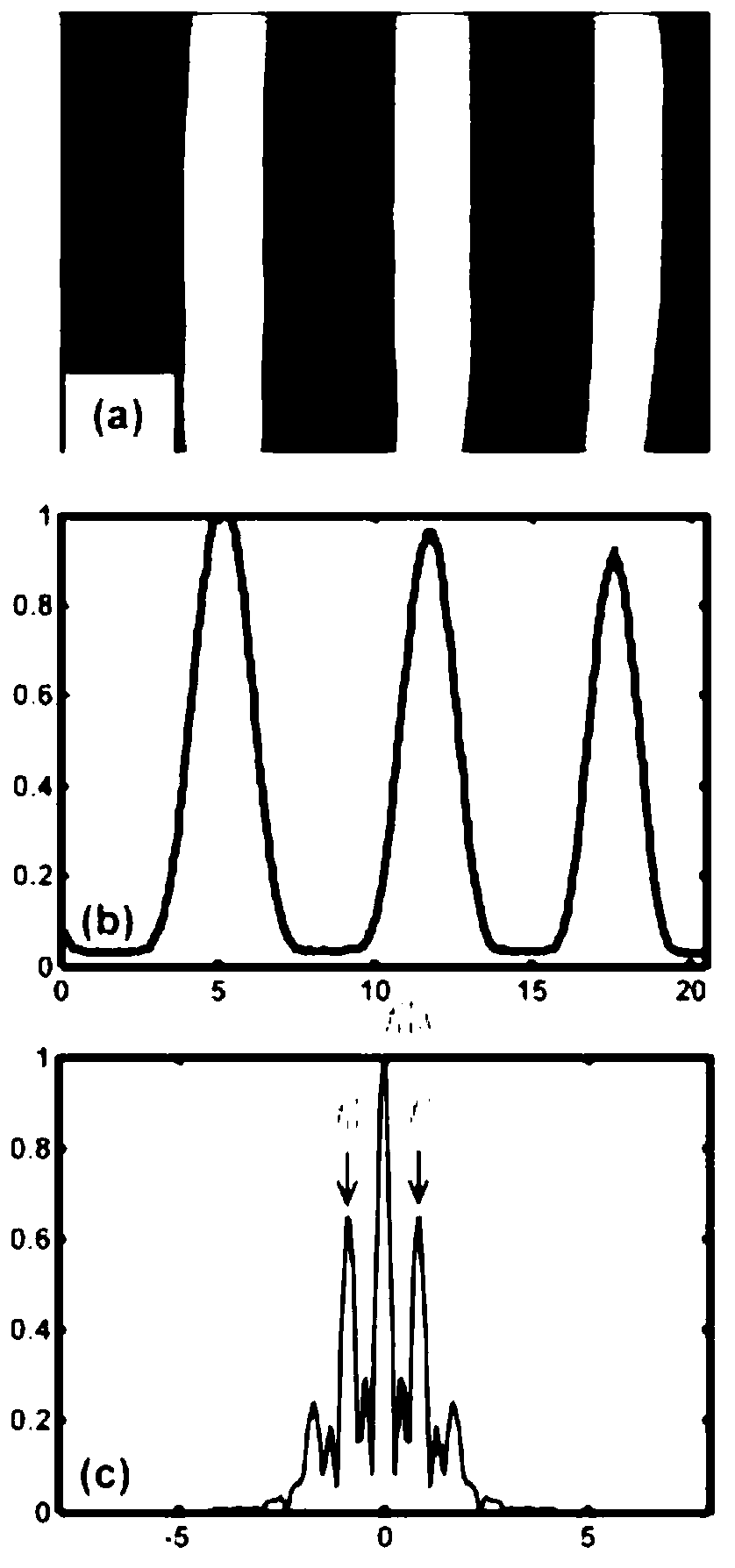
[0031] For comparison, a projector (model CP270, BenQ) with a resolution of 1024*768 will be used to project a standard sinusoidal grating image onto the object under test, and the projection on the object under test will be captured by a CCD camera (model MVD-500SM) Picture, obtain the projection picture with a resolution of 1024*768, as attached figure 2 As shown in (a), the included angle between the shooting angle of the camera and the optical axis of the projector is 20°-40°, and 30° is taken in this embodiment. For comparison, take the gray distributi...


PUM

PropertyMeasurementUnit
Angleaaaaaaaaaa

Abstract

The invention discloses a binary stripe stack based sinusoidal grating generation method. The method provided by the invention comprises the following steps of: firstly generating a sinusoidal grating picture, and decomposing one sinusoidal grating picture into 8 binary pictures through a binary method, wherein each point of each binary picture represents a bit of each point of the original sinusoidal grating after binary, and the value only can be 1 or 1; and through projecting the 8 binary pictures, finally combining the 8 binary pictures into one sinusoidal grating picture. Through the method provided by the invention, a composite plane sinusoidal grating protecting picture E can be obtained, the range of the pixel value of each point of the projecting picture E is from 0 to 255, and is in sinusoidal distribution, and thus errors caused by the nonlinear response of a projector and a camera can be prevented.

Description

technical field [0001] The invention belongs to the field related to the nonlinear response of projectors and cameras. It involves the synthesis of sinusoidal fringe grating. Specifically, it is a sinusoidal grating generation method based on binary fringe superposition. Background technique [0002] Optical 3D measurement is widely used in many fields such as industrial automatic inspection, product quality control, reverse design, biomedicine, virtual reality, cultural relic reproduction, anthropometric measurement, etc. This huge application demand has prompted the rapid development of various optical measurement technologies. With the development of computer technology, digital image acquisition equipment and optical devices, many 3D optical measurement technologies have entered the mature stage of commercial application, and new 3D measurement methods are still emerging. The optical three-dimensional surface shape measurement method based on fringe projection has the...

Claims


Application Information

Patent Timeline
IPC IPC(8): G01B11/25
Inventor 万能常智勇樊迪黄亮张栋梁李春磊
Owner NORTHWESTERN POLYTECHNICAL UNIV
Why Eureka
Try Eureka