Eureka AIR delivers breakthrough ideas for toughest innovation challenges, trusted by R&D personnel around the world.

Fiber bragg grating detection system device and method for detecting anchoring force of anchor rod

A fiber grating and detection system technology, which is applied in the direction of measuring the changing force of optical properties of materials when they are stressed, can solve the problem that the sensor has poor moisture-proof, waterproof and anti-interference performance, cannot well meet the needs of real-time engineering detection, and cannot be Long-term effective detection and other problems, to eliminate the influence of light source power fluctuation and system loss, easy protection and maintenance, and fast detection speed

Inactive Publication Date: 2012-11-28
XIAN UNIV OF SCI & TECH
View PDF4 Cites 44 Cited by
  • Summary
  • Abstract
  • Description
  • Claims
  • Application Information

AI Technical Summary

Problems solved by technology

However, these sensors still have shortcomings such as moisture-proof, waterproof, and anti-interference performance, and cannot realize distributed measurement. At the same time, they still cannot meet the real-time detection needs of the project. In addition, the entire detection process has a long period and equipment installation is extremely cumbersome. Defects that cannot be effectively detected for a long time throughout the process

Method used


Image

  • Fiber bragg grating detection system device and method for detecting anchoring force of anchor rod
  • Fiber bragg grating detection system device and method for detecting anchoring force of anchor rod
  • Fiber bragg grating detection system device and method for detecting anchoring force of anchor rod

Examples


Embodiment 1

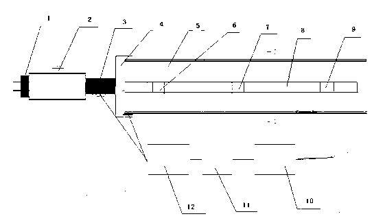
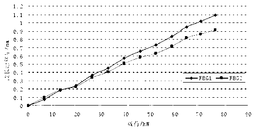
[0042] After connecting the fiber grating anchor detection device with the anchor, the anchoring process of the anchor is detected. Through the fiber grating demodulator software, the data acquisition frequency is set to 2Hz, that is, two groups of fiber grating sensor wavelength data are collected every second, and the average value is taken as the instantaneous wavelength value of the fiber grating at the end of each recording.

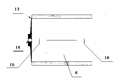
[0043] In a coal mine roadway, the fiber grating sensing method is used to detect the force of the bolt on-line, and the bolt pulling machine is used to carry out the pull test on the bolt. First, install 3 FBG sensors on the anchor rod. A fiber grating anchor dynamometer is installed at the end of the anchor to detect the axial force of the anchor; the anchor specimen and similar materials are put into the prepared steel pipe for anchoring, and after the anchoring is sufficient, the bolt at the free end The anchor head is equipped with a bolt ...


PUM


Abstract

The invention discloses a fiber bragg grating detection system device and method for detecting an anchoring force of an anchor rod. The fiber bragg grating detection system device consists of a fiber bragg grating sensor array, a fiber bragg grating anchor rod dynamometer, a fiber bragg grating demodulator, an optical cable and a computer, wherein the fiber bragg grating anchor rod dynamometer mainly comprises a plurality of fiber bragg grating sensors which are uniformly arranged on an annular elastic body arm and is arranged at the end part of the anchoring end of the anchor rod; meanwhile, the fiber bragg grating sensor array is distributed on a rod body of the anchor rod; the fiber bragg grating sensor array and the fiber bragg grating anchor rod dynamometer are respectively connected with the fiber bragg grating demodulator through the optical cable; and the fiber bragg grating demodulator is connected with the computer. According to the fiber bragg grating detection system device, the real-time detection on the stress of the anchor rod can be realized and the distributed measurement can be realized. The fiber bragg grating detection system device has the advantages of simple structure, convenience in mounting, high detection speed, long-distance monitoring, repeated use and easiness in protection and maintenance, and is widely applied to tunnels and slopes dug for coal mines, metallurgical mines, water conservancy, railways, roads and defense.

Description

technical field [0001] The invention relates to a detection device for detecting and controlling the anchoring quality of an anchor rod, in particular to an optical fiber grating detection system device and a detection method for detecting the anchoring force of an anchor rod through an optical fiber grating to detect the anchoring quality of an anchor rod. Background technique [0002] At home and abroad, anchor bolts are used to stabilize the surrounding rock and slope of caverns and slopes underground or on the ground, and the stability of a large number of roadways, tunnels, and slopes uses bolts to anchor the surrounding rock, especially for underground mining of coal mines, which require a large number of roadways to be excavated underground. According to incomplete statistics, the total length of newly excavated roadways in state-owned large and medium-sized coal mines is as high as 8000km each year, and more than 80% of them are roadways excavated in coal seams. Keepi...

Claims


Application Information

Patent Timeline
Patent Type & Authority Applications(China)
IPC IPC(8): G01L1/24
Inventor 柴敬李毅王道成张桂花
Owner XIAN UNIV OF SCI & TECH
Why Eureka
Eureka Blog
Learn More