
Method for positioning fault memory

A technology for locating faults and memory, which is applied in the detection of faulty computer hardware, hardware monitoring, etc., can solve the problems of inability to meet high-performance computing technology, increase the difficulty of locating faulty memory, test difficulty and complexity, and achieve convenient positioning , reduce complexity, and facilitate memory replacement

Inactive Publication Date: 2012-11-28
LANGCHAO ELECTRONIC INFORMATION IND CO LTD
View PDF2 Cites 22 Cited by
  • Summary
  • Abstract
  • Description
  • Claims
  • Application Information

AI Technical Summary

Problems solved by technology

With the increase in the number of memory, it is more difficult to locate the faulty memory. Once a memory fault occurs, the traditional method of locating the faulty memory is to use a test tool to perform a memory test. Test, and finally find the faulty memory, this method is very difficult and complex
And in the traditional method, as the number of memory bars increases, the difficulty and complexity of the test will increase
On the other hand, the increase in the number of computer memory is an irresistible trend
[0003] This traditional method of locating faulty memory has been unable to meet the development of high-performance computing technology, because this method is suitable for computer applications with a small number of memory

Method used


Image

  • Method for positioning fault memory

Examples


Embodiment Construction

[0008] The present invention will be described in detail below with reference to the accompanying drawings.

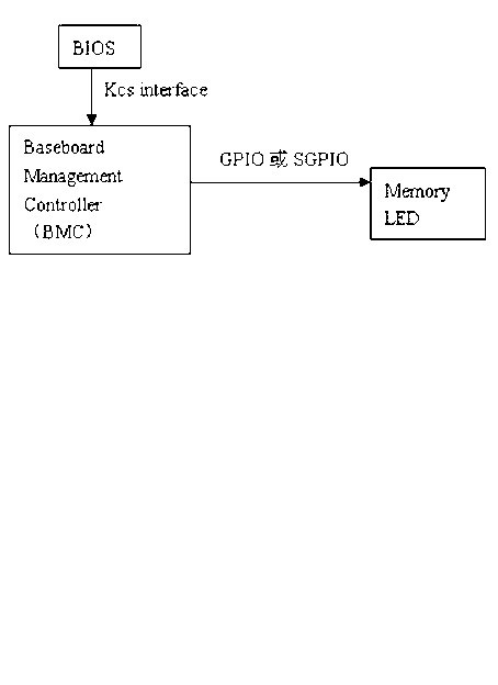
[0009] As described in the summary of the invention, the method for locating the faulty memory mentioned in the present invention uses LED indicators to indicate the location of the faulty memory. First of all, it is necessary to place an LED indicator near each memory so that the LED indicator lights up when a memory failure occurs. Secondly, during the booting process of the BIOS, all memory needs to be detected, and when a memory failure occurs, an IPMI command is organized and sent to the BMC according to the location information of the faulty memory. Finally, the BMC receives and parses the IPMI command sent by the BIOS, obtains the location of the faulty memory, and is responsible for lighting the corresponding LED indicator.

[0010] Compared with the traditional method for locating the faulty memory, the method for locating the faulty memory in the present inv...


PUM


Abstract

The invention provides a method for positioning a fault memory. Each memory corresponds to a light emitting diode (LED) lamp; in system startup process, a basic input / output system (BIOS) detects memories; and if a memory fault is discovered, an intelligent platform management interface (IPMI) command is sent to a baseboard management controller (BMC), the BMC acquires the position of the fault memory according to the IPMI command, and the LED lamp corresponding to the fault memory is turned on, wherein the memory corresponding to the lighting position of the LED lamp is the fault memory. The method comprises the following steps of: (1) starting a system, and detecting the memories by the BIOS; (2) when the BIOS detects the memory fault, organizing the IPMI command according to the position information of the fault memory, and sending the IPMI command to the BMC; and (3) receiving the IPMI command sent by the BIOS by the BMC, resolving the position information of the acquired fault memory, and turning on the LED lamp corresponding to the fault memory.

Description

technical field [0001] The invention relates to the technical field of computer applications, in particular to a method for locating fault memory. Background technique [0002] The development of high-performance computing technology is accompanied by the development of computer technology, as well as the improvement of CPU processing power and memory capacity. Increase. With the increase of the number of memory, the difficulty of locating the faulty memory has increased. Once a memory fault occurs, the traditional method of locating the faulty memory is to use a test tool to perform a memory test. Test, and finally find the faulty memory, this method is very difficult and complex. And in the traditional method, as the number of memory bars increases, the difficulty and complexity of testing will also increase. On the other hand, the increase in the number of computer memories is an irresistible trend. [0003] This traditional method of locating faulty memory has been u...

Claims


Application Information

Patent Timeline
IPC IPC(8): G06F11/22G06F11/32
Inventor 刘宝阳黄家明颜伟平原
Owner LANGCHAO ELECTRONIC INFORMATION IND CO LTD
Learn More