
Flyback-type quick-start LED (Light-Emitting Diode) drive circuit structure

A technology of LED driving and fast startup, which is applied in the layout of electric lamp circuits, electric light sources, lighting devices, etc., can solve the problems of difficulty in achieving a compromise solution between the driving efficiency and startup time of LED driving circuits, and high power consumption, so as to improve the driving efficiency. , the effect of reducing power consumption and reducing start-up resistance

Active Publication Date: 2012-11-28
宿松县市场监督管理局市场监督检验所
View PDF7 Cites 28 Cited by
  • Summary
  • Abstract
  • Description
  • Claims
  • Application Information

AI Technical Summary

Problems solved by technology

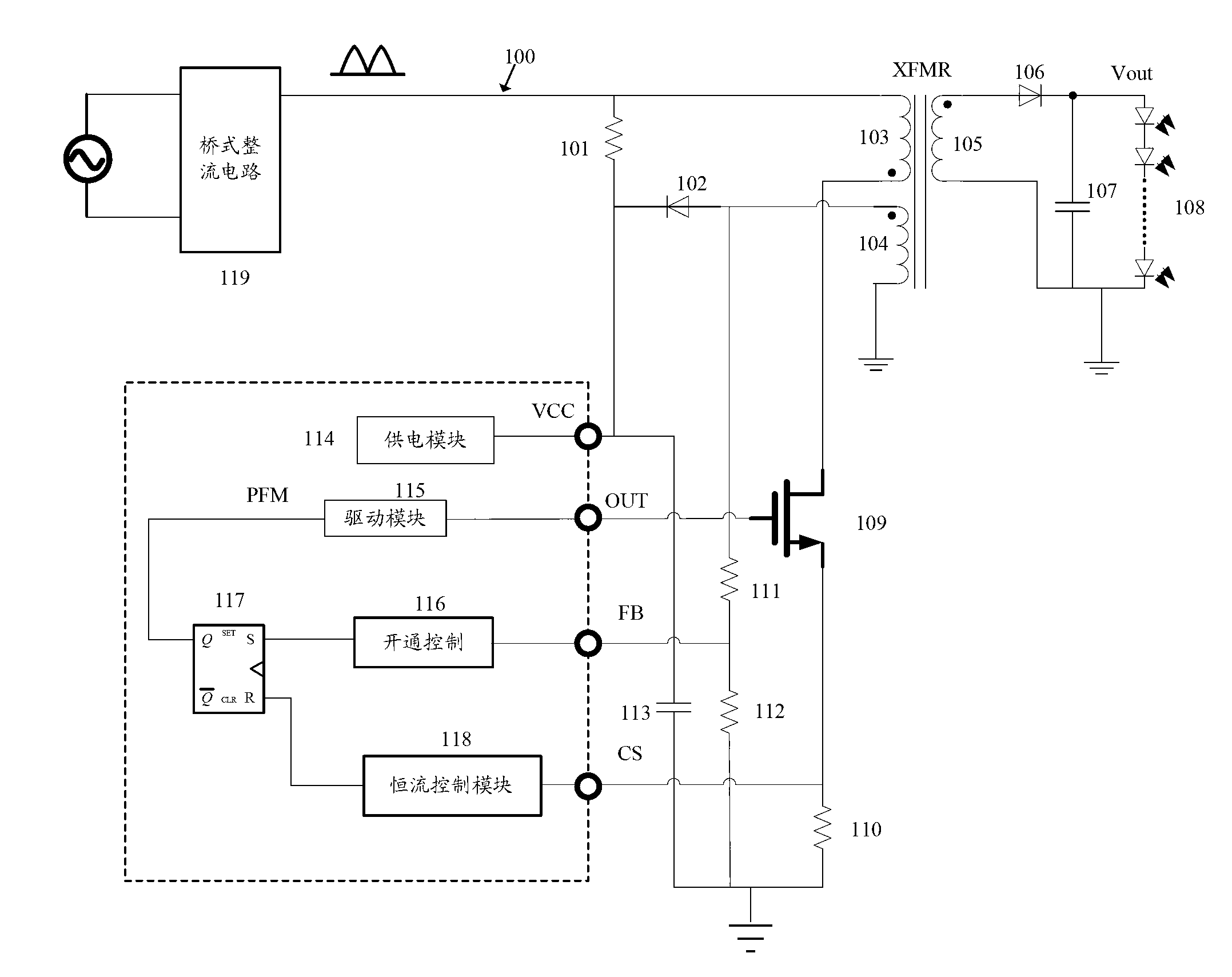
[0005] The above-mentioned LED driving circuit has the following two disadvantages: first, the AC line voltage 100 charges VCC through the starting resistor 101, usually the driving circuit works at about 11V, and the voltage on the power line 100 is usually a high voltage above 200V. On the resistor 101, there will be a voltage drop of several hundred volts, and the power consumption will be large
[0010] As mentioned above, as figure 1 It is difficult for the LED driving circuit in the prior art to achieve a good compromise between driving efficiency and start-up time

Method used


Image

  • Flyback-type quick-start LED (Light-Emitting Diode) drive circuit structure
  • Flyback-type quick-start LED (Light-Emitting Diode) drive circuit structure
  • Flyback-type quick-start LED (Light-Emitting Diode) drive circuit structure

Examples


Embodiment Construction

[0024] In order to understand the technical aspects of the present invention more clearly, the following examples are given in detail.

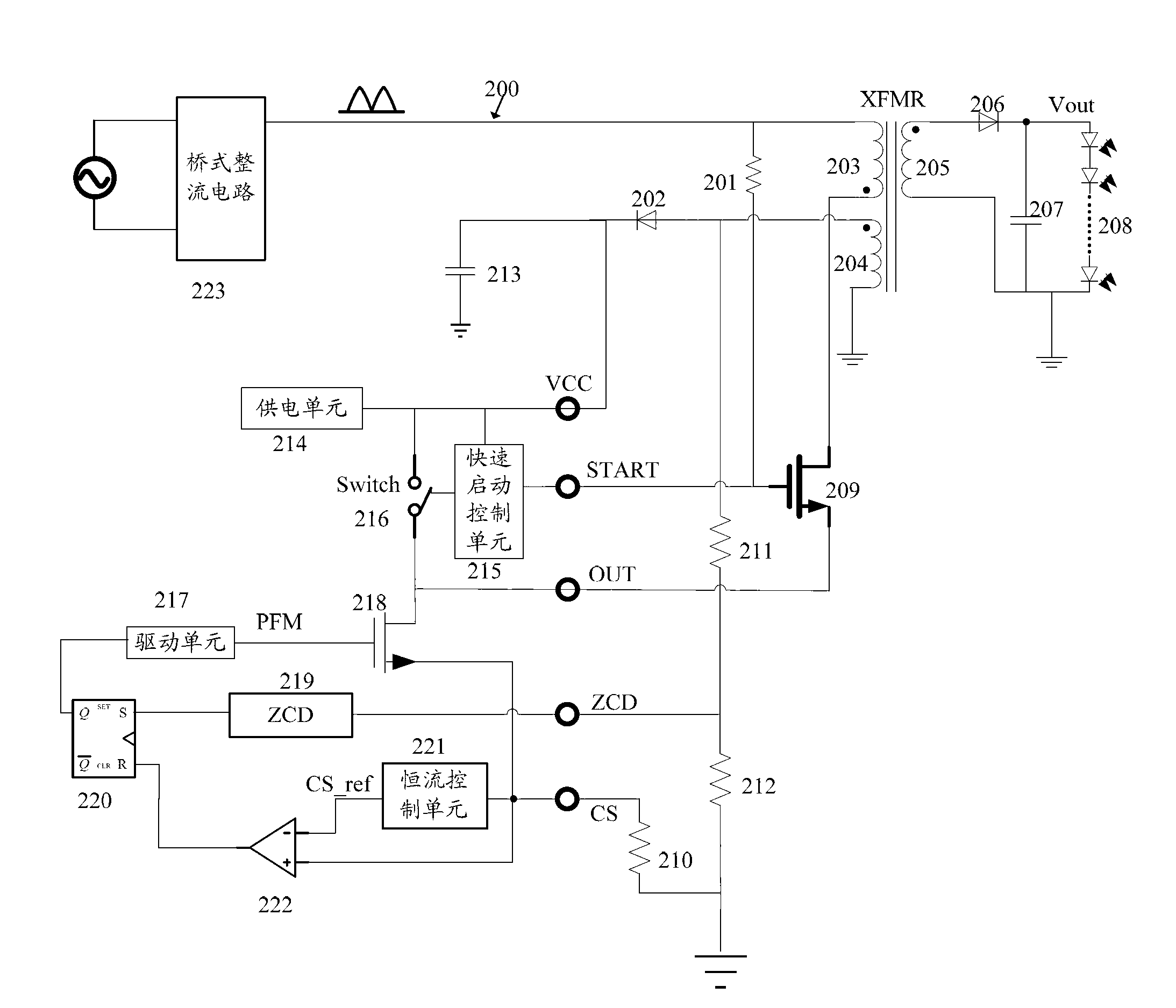
[0025] see figure 2 As shown, the present invention is a schematic diagram of the structure of the flyback fast-start LED driving circuit of the present invention.

[0026] In one embodiment, the circuit structure includes a voltage input module, a load output module, a transformer, a feedback control circuit module and a quick start control circuit module.

[0027] Such as figure 2 As shown, wherein the transformer includes a primary winding 203 , a secondary winding 205 and a secondary winding 204 . The voltage input module is connected to the opposite terminal of the primary winding 203 of the transformer. The load output module is connected to the secondary winding 205 of the transformer. The feedback control circuit module is respectively connected to the secondary winding 204 and the fast start control circuit module. The quick sta...


PUM


Abstract

The invention relates to a flyback-type quick-start LED (Light-Emitting Diode) drive circuit structure, belonging to the technical field of circuit structures. The circuit structure comprises a voltage input module, a load output module, a transformer, a feedback control circuit module and a quick-start control circuit module, wherein an output end of the quick-start control unit is connected with a control end of a switch; the switch is connected between a source electrode of an external power tube and an output end VCC (Collector Supply Voltage) of a power supply unit and is connected with one end of the source electrode of the external power tube and an output end of the feedback control circuit module. According to the invention, the source drive of the quick-start control unit is realized, in addition, power is supplied to a control circuit from the source electrode through the switch, starting resistance is reduced, meanwhile, the quiescent current of a drive module is reduced, and the power consumption is reduced; and quick start within 200ms is realized, the drive efficiency is improved, meanwhile, the actual area and the cost of the circuit structure are reduced, and a wider application range is achieved.

Description

technical field [0001] The present invention relates to the technical field of circuit structure, in particular to the technical field of LED drive circuit structure, and specifically refers to a flyback fast-start LED drive circuit structure. Background technique [0002] At present, high-power LED drivers usually need to meet the following conditions: high power factor, constant output current, electrical isolation, high efficiency, fast start-up, etc. In order to ensure a constant luminous intensity, constant output current is the basic requirement of LED drivers; electrical isolation must be followed for safety reasons; the efficiency of the driving power supply is particularly important for the structure in which the power supply is installed in the lamp. Since the luminous efficiency of LED decreases with the increase of LED temperature, the heat dissipation of LED is also very important. The power supply has high efficiency, its power consumption is small, and the hea...

Claims


Application Information

Patent Timeline
IPC IPC(8): H05B37/02
Inventor 田剑彪杜大海朱振东孙菊根聂海英胡建伟
Owner 宿松县市场监督管理局市场监督检验所
Learn More