Float transaction wave power generating device

A wave power generation and dynamic technology, applied in ocean energy power generation, engine components, machines/engines, etc., can solve the problems of low secondary energy conversion efficiency, low secondary energy conversion rate, and terrain requirements, and achieve novel structure. , the effect of improving utilization, construction difficulty and low cost

Inactive Publication Date: 2012-12-05
TIANJIN UNIV
View PDF5 Cites 10 Cited by
  • Summary
  • Abstract
  • Description
  • Claims
  • Application Information

AI Technical Summary

Problems solved by technology

The disadvantage is that the secondary energy conversion efficiency is low
The disadvantage is that the construction of the power station has requirements on the terrain and is not easy to promote
The above-mentioned technical devices all use three-stage links to convert wave energy. The energy receiving body directly receives the energy transmitted from the waves, and the fixed body generates energy through relative motion with the energy receiving body. The intermediate conversion device, which The conversion device mainly plays the role of stabilizing direction, increasing speed and stabilizing speed, but in summary of the above wave energy conversion devices, the secondary conversion rate of energy is relatively low

Method used


Image

  • Float transaction wave power generating device
  • Float transaction wave power generating device
  • Float transaction wave power generating device

Examples


Embodiment 1

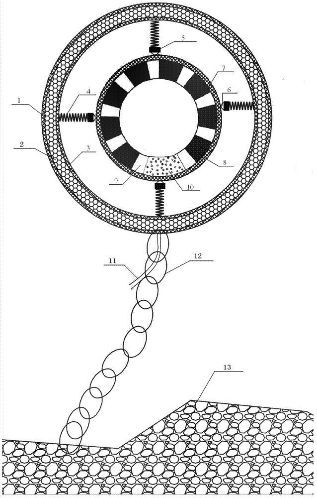
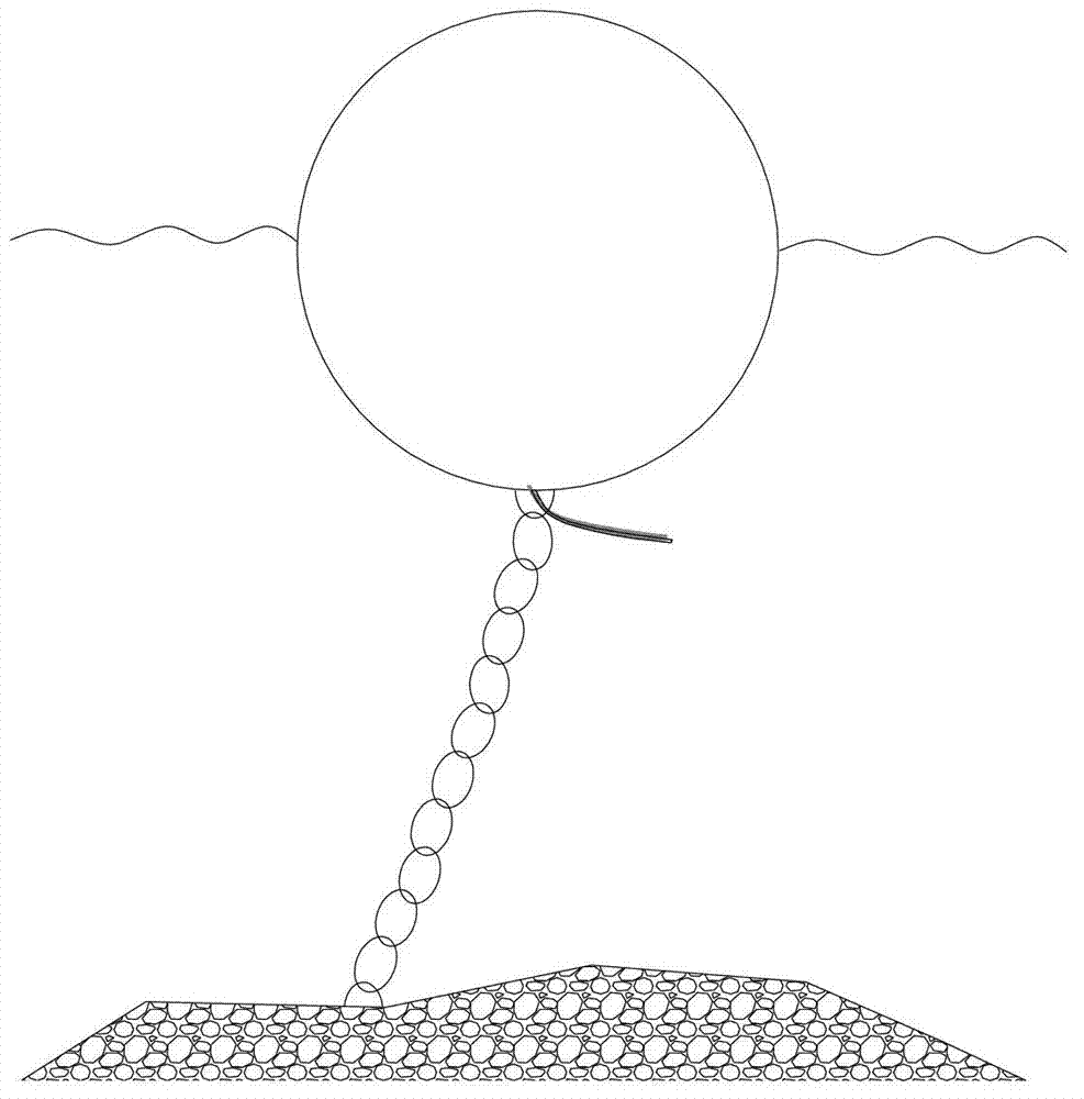
[0022] see Figure 1 ~ Figure 2 , a kind of floating floating wave power generation device, including an external float and an internal float placed inside; the external float includes a non-magnetic insulating layer 3 and a closed outer float shell 1 placed outside the non-magnetic insulating layer 3, and the closed outer float A chamber is formed between the float housing 1 and the non-magnetic insulating layer 3. The cross section of the chamber at the center of the outer float is circular, and the electronic coil 2 wound according to the winding method of the generator coil is fixed in the chamber; the outer float housing 1 Protect its internal structure from being damaged by water bodies.

[0023] The inner float includes an inner float housing 7 made of non-magnetic wear-resistant material, and a plurality of magnets 8 and counterweights 10 are evenly distributed and fixed in the inner float housing 7 along its cross-section circumferential direction, and all magnets 8 a...

Embodiment 2

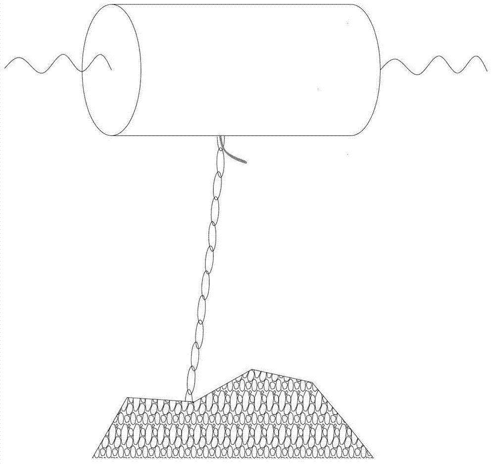
[0029] see figure 1 and image 3 , The only difference from Embodiment 1 is that the outer surfaces of the closed outer float shell and the inner float shell are both cylindrical, and the inner float shell can be either open or closed. image 3 cross section with figure 2 The section structure through the center of the closed outer float shell is the same, such as figure 1 shown.

[0030] To sum up, the present invention directly utilizes the energy generated by wave motion, with the help of the outer float swinging back and forth or floating up and down, and the abnormal movement of the inner suspension magnet and the outer float, so that the magnetic flux passing through the electronic coil changes, thereby generating current, reducing the intermediate Link energy consumption, so that the utilization rate of wave energy is greatly improved.


PUM


Abstract

The invention discloses a float transaction wave power generating device, which includes an outer float and an inner float arranged in the outer float, wherein the outer float includes a non-magnetic insulation layer, an enclosed outer float housing arranged outside the layer and an electronic coil arranged between the layer and the housing; the inner float includes an inner float housing made of non-magnetic wear-resistant material, a plurality of uniformly distributed magnets and counter weights are fixed in the inner float housing, and the inner float housing is connected with the non-magnetic insulation layer through multiple sets of elastic mechanisms; the enclosed outer float housing is connected with a sea bed rock through an anchor chain; and an output conducting wire is connected with the electronic coil. By directly utilizing the energy produced by wave motion, and by virtue of the back-forth swinging or up-down floating of the outer float and the transaction of the internally suspended magnets and the outer float, the magnetic flux of the electronic coil is changed, so as to generate current, as a result, the consumption of the energy in the intermediate link is reduced, and the wave energy utilization rate is greatly improved.

Description

technical field [0001] The invention relates to a device for generating electricity by utilizing ocean wave energy, in particular to a float-alteration type wave power generation device, which belongs to the technical field of new renewable energy. Background technique [0002] With the development of the world economy, the surge of population, and the progress of society, the human demand for energy is increasing day by day. Human beings are facing severe challenges in the development of traditional energy sources. The development cost of traditional energy has become more expensive with the increasingly scarce resources, and with the continuous consumption of human beings, the world's main energy development period has been numbered: about 30-40 years for oil, natural gas and uranium, and about 30-40 years for coal. 200 or so. People have to turn to the development and research in the marine field to find new development space. There are abundant resources in the ocean,...

Claims


Application Information

Patent Timeline
Patent Type & Authority Applications(China)
IPC IPC(8): F03B13/16
CPCY02E10/38Y02E10/30
Inventor 李大鸣范玉罗浩
Owner TIANJIN UNIV
Why Eureka
Try Eureka