Three-dimensional heat-pipe heat exchanger and production method thereof

A heat exchanger and three-dimensional heat pipe technology, applied in the field of heat transfer, can solve the problems of fixed structure, difficult heat pipe manufacturing, impractical application, etc.

Inactive Publication Date: 2012-12-05
苏州浩佳节能科技有限公司
View PDF4 Cites 24 Cited by
  • Summary
  • Abstract
  • Description
  • Claims
  • Application Information

AI Technical Summary

Problems solved by technology

However, this converging heat pipe structure is relatively fixed, and the serpentine coil used requires additional machining, and it is necessary to connect the converging pipe to the end of each U-shaped pipe
As a result, such heat pipes are relatively difficult to manufacture, making their use in many applications, including many conventional air conditioning systems, impractical

Method used


Image

  • Three-dimensional heat-pipe heat exchanger and production method thereof
  • Three-dimensional heat-pipe heat exchanger and production method thereof
  • Three-dimensional heat-pipe heat exchanger and production method thereof

Examples


Embodiment Construction

[0053] The present invention will be further described below in conjunction with the accompanying drawings.

[0054] According to the present invention, the heat pipe heat exchanger is in the form of serpentine heat pipes, and through the connection of U-shaped pipes, the heat pipes can form a fully continuous coil.

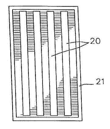
[0055] Such as Figure 3B As shown, in the heat pipe heat exchanger 38 manufactured according to the present invention, the open ends of adjacent U-shaped pipes 30 are connected to each other through a U-shaped elbow 31 , thereby forming a serpentine heat pipe 36 . Heat conduction fins 32 , preferably aluminum fins, are sheathed on the outside of the heat pipe to form a serpentine heat pipe heat exchanger 38 . Each U-shaped pipe 30 does not use a liquid-absorbing core, but makes micro-grooves 33 on the inner wall of the pipe, so that more heat can be transmitted.

[0056] Figure 3B Before using the heat pipe heat exchanger 38 shown in , a predetermined amount...


PUM


Abstract

The invention discloses a three-dimensional heat-pipe heat exchanger. A plurality of pipes are combined into an S-shaped heat pipe by a U-shaped elbow, and the heat-pipe heat exchanger connected by the U-shaped elbow can form a completely continuous coiled pipe. The S-shaped heat pipe and the heat exchanger can be configured into an integrative heat exchanger, wherein a condensing end and an evaporating end are isolated by a heat insulation section, or can be configured into a split type heat exchanger, wherein the evaporating end and the condensing end are connected by an evaporating pipe and a reflowing pipe. The three-dimensional heat-pipe heat exchanger can form a continuous closed loop, in this way, the heat exchanger works no matter whether the reflowing is implemented with the aid of gravity. A plurality of U-shaped pipes are needed to interconnect in the production of the S-shaped pipe to form one S-shaped heat pipe loop, wherein one pipe has an opening end, each of all the pipes can work as one independent heat pipe only by injecting enough refrigerant from the opening end at one time. The three-dimensional heat-pipe heat exchanger can be used for the aspects of enhancement of dehumidification effect of the air conditioner, energy recovering, heat radiation of partial space, and the like.

Description

[0001] technical field [0002] The invention relates to the field of heat transfer technology, in particular to an "air-air" system, which uses the principle of absorbing or releasing heat during the phase change of the working medium, and can transmit very high heat flow without inputting additional energy 3D heat pipe heat exchanger. Background technique [0003] The so-called heat pipe usually includes a condensing end and an evaporating end, and the condensing end and the evaporating end are connected to each other to form a closed system. refer to figure 1 , a typical heat pipe 6 is composed of a closed pipe 8 , one end of the pipe 8 constitutes the evaporation end 10 , and the other end, which has a lower temperature and pressure, constitutes the condensation end 12 . The liquid-absorbing wick 14 runs through the entire heat pipe from the evaporating end 10 to the condensing end 12 . Through the auxiliary heat dissipation of the fins 15, the heat can be transferred...

Claims


Application Information

Patent Timeline
Patent Type & Authority Applications(China)
IPC IPC(8): F28D15/02
CPCF28D15/0266
Inventor 李跃
Owner 苏州浩佳节能科技有限公司
Why Eureka
Try Eureka